
User manual

Publication CIG-WD001B-EN-P - May 2005
1756 ControlLogix I/O Modules 7-7
12
34
56
78
910
1112
1314
1516
1718
1920
2122
2324
2526
2728
2930
3132
3334
3536
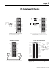
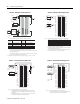
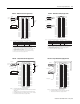
+IN-1/V
IN-1/I
-IN-1
+IN-3/V
V OUT-1
IN-3/I
-IN-3
Not used
Not used
I OUT-1
RTN-1
Not used
+IN-0/V
IN-0/I
-IN-0
+IN-2/V
IN-2/I
-IN-2
2-Wire
Transmitter
A
A
A
(+) (-) i
i
Shield
ground
Current
Output
Load
Not used
Not used
Not used
Not used
Not used
Not used
V OUT-0
Not used
Not used
I OUT-0
Not used
Not used
Not used
Not used
Not used
Not used
Not used
RTN-0
NOTE: Place additional loop devices (e.g. strip chart recorders) at any A location.
12
34
56
78
910
1112
1314
1516
1718
1920
2122
2324
2526
2728
2930
3132
3334
3536
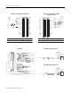
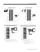
User
Analog
Input
Device
(+)
(-)
Shield
ground
(+)
(+)
(-)
Shield
ground
+IN-1/V
IN-1/I
-IN-1
+IN-3/V
V OUT-1
IN-3/I
-IN-3
Not used
Not used
I OUT-1
RTN-1
Not used
+IN-0/V
IN-0/I
-IN-0
+IN-2/V
IN-2/I
-IN-2
Not used
Not used
Not used
Not used
Not used
Not used
V OUT-0
Not used
Not used
I OUT-0
Not used
Not used
Not used
Not used
Not used
Not used
Not used
RTN-0
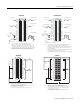
1756-IF4FXOF2F Current Mode 1756-IF4FXOF2F Voltage Mode
+–
1
2
3
4
56
78
910
1112
1314
1516
1718
1920
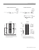
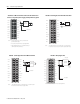
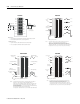
VOUT-1
IN-1/I
RTN-1
VOUT-3
IN-3/I
RTN-3
Not used
VOUT-5
IN-5/I
RTN-5
VOUT-0
IN-0/I
RTN-0
VOUT-2
IN-2/I
RTN-2
Not used
VOUT-4
IN-4/I
RTN-4
2-Wire
Transmitter
24V dc
Shield ground
NOTES:
1. If separate power sources are used, do not exceed the
specified isolation voltage.
2. Do not connect more than 2 wires to any single terminal.
3. Place additional loop devices (e.g. strip chart recorders) at
either A location in the current loop.
i
A
A
1756-IF6CIS - 2-Wire transmitter connected to the module
and the module providing 24V dc loop power
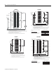
1756-IF6CIS - 2-Wire transmitter connected to the module and an
external, user-provided power supply providing 24V dc loop power
+
–
1
2
3
4
56
78
910
1112
1314
1516
1718
1920
VOUT-1
IN-1/I
RTN-1
VOUT-3
IN-3/I
RTN-3
Not used
VOUT-5
IN-5/I
RTN-5
VOUT-0
IN-0/I
RTN-0
VOUT-2
IN-2/I
RTN-2
Not used
VOUT-4
IN-4/I
RTN-4
2-Wire
Transmitter
Shield ground
NOT ES:
1. Do not connect more than 2 wires to any single terminal.
2. Place additional loop devices (e.g. strip chart recorders) at either
A location in the current loop.
A
i
A