
User manual

Publication CIG-WD001B-EN-P - May 2005
7-6 1756 ControlLogix I/O Modules
12
34
56
78
910
1112
1314
1516
1718
1920
2122
2324
2526
2728
2930
3132
3334
3536
+
–
+
–
Shield ground
Channel 0
Channel 3
IN-0
IN-1
IN-2
IN-3
IN-7
RTN
IN-4
IN-5
IN-6
IN-15
IN-8
IN-9
IN-10
IN-11
RTN
IN-12
IN-13
IN-14
i RTN-0
i RTN-1
i RTN-2
i RTN-3
i RTN-7
RTN
i RTN-4
i RTN-5
i RTN-6
i RTN-15
i RTN-8
i RTN-9
i RTN-10
i RTN-11
RTN
i RTN-12
i RTN-13
i RTN-14
Shield ground
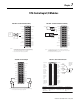
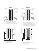
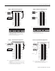
1. Use the following chart when wiring your module in differential mode
2. When operating in 4 channel, high speed mode, only use channels 0, 2, 4 and
6
3. All terminals marked RTN are connected internally.
4. If multiple (+) or multiple (-) terminals are tied together, connect that tie point to
terminal to maintain the module’s accuracy.
5. Terminals marked RTN and i RTN are not used for differential voltage wiring.
This channel : Uses these inals: This channel: Uses these terminals:
Channel 0 IN-0 (+) & IN-1 (-) Channel 4 IN-8 (+) & IN-9 (-)
Channel 1 IN-2 (+) & IN-3 (-) Channel 5 IN-10 (+) & IN-11 (-)
Channel 2 IN-4 (+) & IN-5 (-) Channel 6 IN-12 (+) & IN-13 (-)
Channel 3 IN-6 (+) & IN-7 (-) Channel 7 IN-14 (+) & IN-15 (-)
NOTES:
term
6. Do not connect more than 2 wires to any single terminal.
12
34
56
78
910
1112
1314
1516
1718
1920
2122
2324
2526
2728
2930
3132
3334
3536
IN-0
IN-10
IN-1
IN-9
IN-2
IN-8
IN-5
IN-3
IN-6
RTN
IN-7
IN-4
IN-13
IN-12
IN-14
IN-11
RTN
i RTN-0
i RTN-7
i RTN-4
i RTN-6
i RTN-8
i RTN-9
i RTN-10
i RTN-11
RTN
i RTN-12
i RTN-13
RTN
i RTN-5
i RTN-1
i RTN-2
i RTN-3
IN-15
i RTN-14
i RTN-15
Shield ground
Channel 0
Channel 3
Jumper
wires
i
i
A
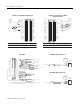
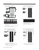
NOTES:
1.
2. All terminals marked RTN are connected internally.
3. A 249 current loop resistor is located between IN-x and i RTN-x terminals.
4. If multiple (+) or multiple (-) terminals are tied together, connect that tie point to a RTN terminal to
maintain the module’s accuracy.
5. Place additional loop devices (e.g. strip chart recorders, etc.) at the A location in the current loop.
6. Do not connect more than two wires to any single terminal.
IMP ORTANT: When operating in 4 ch annel, high speed mo de, only use channels 0, 2, 4 and 6.
Th is
chan nel :
Uses t hese terminal s: Th is
ch ann el :
Uses t hese t erm inal s:
Channel 0 IN-0 (+), IN-1 (-) & i RTN-0 Channel 4 IN-8 (+), IN-9 (-) & i RTN-8
Channel 1 IN-2 (+), IN-3 (-) & i RTN-2 Channel 5 IN-10 (+), IN-11 (-) & i RTN-10
Channel 2 IN-4 (+), IN-5 (-) & i RTN-4 Channel 6 IN-12 (+), IN-13 (-) & i RTN-12
Channel 3 IN-6 (+), IN-7 (-) & i RTN-6 Channel 7 IN-14 (+), IN-15 (-) & i RTN-14
2-Wire
Transmitter
A
+
–
4-Wire
Transmitter
24V dc
Shield ground
+
–
Channel 6
i
A
Use the table below when wiring your module in differential current mode.
1756-IF16 – Differential Current Applications 1756-IF16 – Differential Voltage Applications
12
34
56
78
910
1112
1314
1516
1718
1920
2122
2324
2526
2728
2930
3132
3334
3536
+
–
+
–
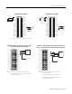
Shield
ground
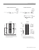
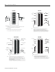
1. All terminals marked RTN are connected internally.
2. Terminals marked i RTN are not used for single-ended voltage wiring.
IN-0
IN-1
IN-2
IN-3
IN-7
RTN
IN-4
IN-5
IN-6
IN-15
IN-8
IN-9
IN-10
IN-11
RTN
IN-12
IN-13
IN-14
i RTN-0
i RTN-1
i RTN-2
i RTN-3
i RTN-7
RTN
i RTN-4
i RTN-5
i RTN-6
i RTN-15
i RTN-8
i RTN-9
i RTN-10
i RTN-11
RTN
i RTN-12
i RTN-13
i RTN-14
Shield
ground
NOTES:
3. Do not connect more than 2 wires to any single terminal.
12
34
56
78
910
1112
1314
1516
1718
1920
2122
2324
2526
2728
2930
3132
3334
3536
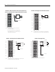
Shield
ground
Jumper
wires
i
i
A
2-Wire
Transmitter
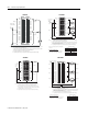
1. All terminals marked RTN are connected internally.
2. A 249 current loop resistor is located between IN-x and i RTN-x terminals.
3. For current applications, all terminals marked i RTN must be wired to terminals
marked RTN.
4. Place additional loop devices (e.g. strip chart recorders, etc.) at A location.
IN-0
IN-1
IN-2
IN-3
IN-7
RTN
IN-4
IN-5
IN-6
IN-15
IN-8
IN-9
IN-10
IN-11
RTN
IN-12
IN-13
IN-14
i RTN-0
i RTN-1
i RTN-2
i RTN-3
i RTN-7
RTN
i RTN-4
i RTN-5
i RTN-6
i RTN-15
i RTN-8
i RTN-9
i RTN-10
i RTN-11
RTN
i RTN-12
i RTN-13
i RTN-14
NOTES:
Ω
the
5. Do not connect more than 2 wires to any single terminal.
1756-IF16 – Single-Ended Current Applications 1756-IF16 – Single-Ended Voltage Applications