
User manual

Publication CIG-WD001B-EN-P - May 2005
7-4 1756 ControlLogix I/O Modules
12
34
56
78
910
11
12
1314
1516
1718
19
20
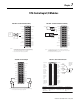
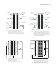
47kΩ, 1/2W,
5% resistor
47kΩ, 1/2W,
5% resistor
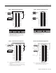
1. All terminals with the same name are connected together on the module. For example,
L2 can be connected to any terminal marked L2-0.
2. This wiring example shows a single voltage source.
3. When you daisy chain from a group to other RTBs, alway connect the daisy chain to the
terminal directly connected to the supply wire, as shown above.
4. If separate power sources are used, do not exceed the specified isolation voltage.
Resistors are not necessary if Wire Off diagnostic
is not used.
To Determine Leakage Resistor
(P/S = Field side power supply)
R
LEAK
Maximum = (P/S Voltage-19V ac)/1.5mA
R
LEAK
Minimum = (P/S Voltage-20V ac)/2.5mA
Not used
L2-0
L2-0
L2-0
L2-0
L2-1
L2-1
L2-1
L2-1
L2-1
L1-0 Loss of Field Power
IN-0
IN-1
IN-2
IN-3
IN-4
IN-5
IN-6
IN-7
L1-1 Loss of Field Power
Daisy chain to
other RTBs
Group
0
Group 0
Group
1
Group 1
L2
L1
Recommended Values
P/S Voltage R
LEAK,
1/2W, 5%
43kΩ
47kΩ
47kΩ
51kΩ
NOTES:
100V ac +/-10%
110V ac +/-10%
115V ac +/-10%
120V ac +/-10%
Do not connect more
than 2 wires to any single terminal.
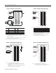
1. All terminals with the same name are connected together on the module. For example, L2 can
be connected to any terminal marked L2-0.
2. When you daisy chain from a group to another RTB, always connect the daisy chain as shown
above. Do not connect more than 2 wires to any single terminal.
3. This wiring example shows a single voltage source.
4. If separate power sources are used, do not exceed the specified isolation voltage.
NOTES:
12
34
56
78
910
1112
1314
1516
1718
1920
2122
2324
2526
2728
2930
3132
3334
3536
IN-0
IN-2
IN-4
IN-6
IN-8
IN-10
IN-12
IN-14
IN-16
IN-18
IN-20
IN-22
IN-24
IN-26
IN-28
IN-30
L2-1
L2-0
IN-1
IN-3
IN-5
IN-7
IN-9
IN-11
IN-13
IN-15
L2-0
IN-17
IN-19
IN-21
IN-23
IN-25
IN-27
IN-29
IN-31
L2-1
L1
L2
Daisy chain
to other RTBs
Group 1 Group 1
Group 0 Group 0
1756-IA8D
1756-IA32
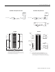
IN-9
IN-11
IN-13
IN-15
GND-1
IN-1
IN-3
IN-5
IN-7
GND-0
IN-8
IN-10
IN-12
IN-14
GND-1
IN-0
IN-2
IN-4
IN-6
GND-0
12
34
5
6
7
8
910
11
12
1314
1516
1718
19
20
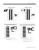
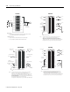
1. All terminals with the same name are connected together on the module. For
example, DC COM can be connected to either terminal marked GND-0.
2. When you daisy chain from a group to another RTB, always connect the daisy
chain as shown above. Do not connect more than 2 wires to any single terminal.
3. This wiring example shows a single voltage source.
4. If separate power sources are used, do not exceed the specified isolation voltage.
–+
Daisy chain
to other
RTBs
Group 0
Group 0
Group 1Group 1
DC COM
NOTES:
1756-IB16
12
34
56
78
910
1112
1314
1516
1718
1920
2122
2324
2526
2728
2930
3132
3334
3536
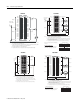
+–
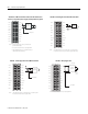
14.3kΩ, 1/4W,
2% resistor
14.3kΩ, 1/4W,
2% resistor
1. All terminals with the same name are connected together on the module.
2. This wiring example shows a single voltage source.
3. When you daisy chain from a group to other RTBs, alway connect the daisy chain to the
terminal directly connected to the supply wire, as shown above.
4. Resistors are not necessary if Wire Off diagnostic is not used.
5. If separate power sources are used, do not exceed the specified isolation voltage.
To Determine Leakage Resistor
(P/S = Field side power supply)
R
LEAK
Maximum = (P/S Voltage- 4.6V dc)/1.21mA
R
LEAK
Minimum = (P/S Voltage- 5V dc)/1.5mA
Daisy chain to other RTBs
Group 0
Group 1
Recommended Values
P /S Voltage R
LEAK,
1/4W, 2%
5.23k Ω
14.3k Ω
Group 2
Group 3
Group 0
Group 1
Group 2
Group 3
IN-0
IN-1
IN-2
IN-3
IN-8
IN-4
IN-5
IN-6
IN-7
Not used
IN-9
IN-10
IN-11
IN-12
IN-13
IN-14
IN-15
Not used
GND-0
GND-0
GND-0
GND-0
GND-2
GND-1
GND-1
GND-1
GND-1
Not used
GND-2
GND-2
GND-2
GND-3
GND-3
GND-3
GND-3
GND-3
DC COM
NOTES:
12V dc +/-5%
24V dc +/-5%
Do not connect more
than 2 wires to any single terminal.
1756-IB16D