
User manual

Publication CIG-WD001B-EN-P - May 2005
7-2 1756 ControlLogix I/O Modules
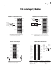
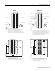
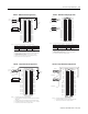
Appl ic ation : A0 Conne cti ons: B 0 Co nne cti ons: Z0 Con nect ions :
PNP (Sourcing)
N.O.
Black - A0 (12-24V)
Blue, PS(-)- A0 (RET)
Jumper B0 (12-24V) to
B0 (RET)
Jumper Z0 (12-24V) to
Z0 (RET)
12
34
56
78
910
1112
1314
1516
1718
1920
2122
2324
2526
2728
2930
3132
3334
3536
Jumpers
Black
Blue
Allen-Bradley
Bulletin 872
3-Wire DC
Proximity
Sensor
Z1 (12-24V)
Z1 (5V)
Z1 (RET)
B1 (12-24V)
B1 (5V)
B1 (RET)
A1 (12-24V)
A1 (5V)
A1 (RET)
Not used
Not used
Not used
Z0 (12-24V)
Z0 (5V)
Z0 (RET)
B0 (12-24V)
B0 (5V)
B0 (RET)
A0 (12-24V)
A0 (5V)
A0 (RET)
Not used
Not used
Not used
COMMON 0
COMMON 0
COMMON 0
DC-0(+)
Out 2
Out 3
COMMON 1
COMMON 1
COMMON 1
DC-1(+)
Out 0
Out 1
12-24V dc
Return
12-24V dc
NOTE: Do not connect more than 2 wires to any single terminal.
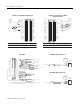
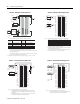
Appl ic ation : A1 Co nne cti ons: B 1 Co nne cti ons: Z1 Con nect ions :
Any Black - A1 (12-24V)
Blue - A1 (RET)
Jumper B1 (12-24V) to
B1 (RET)
White - Z1 (12-24V)
Blue - Z1 (RET)
12
34
56
78
910
1112
1314
1516
1718
1920
2122
2324
2526
2728
2930
3132
3334
3536
Jumper
Black
Blue
White
Not used
10-30V dc
Photoswitch
Series 10,000
Photoelectric
Sensor
Z1 (12-24V)
Z1 (5V)
Z1 (RET)
B1 (12-24V)
B1 (5V)
B1 (RET)
A1 (12-24V)
A1 (5V)
A1 (RET)
Not used
Not used
Not used
Z0 (12-24V)
Z0 (5V)
Z0 (RET)
B0 (12-24V)
B0 (5V)
B0 (RET)
A0 (12-24V)
A0 (5V)
A0 (RET)
Not used
Not used
Not used
COMMON 0
COMMON 0
COMMON 0
DC-0(+)
Out 2
Out 3
COMMON 1
COMMON 1
COMMON 1
DC-1(+)
Out 0
Out 1
12-24V dc
Return
NOTE: Do not connect more than 2 wires to any single terminal.
1756-HSC - 872 3-Wire DC Proximity Sensor 1756-HSC - Photoswitch Series 10,000
Photoelectric Sensor
+O UT-0
-OU T-0
+E NABLE- 0
-ENA BL E-0
DR VFLT-0
CHASSIS
IN_CO M
HO ME-0
RE G24V-0
REG5 V-0
+O K
CHASSIS
+IN T-0
-INT-0
+R ET-0
-RET-0
LD T C MN
CHASSIS
+O UT-1
-OUT-1
+EN ABLE- 1
-EN AB LE-1
DR VFLT-1
CH AS SIS
IN_CO M
HO ME -1
REG 24V-1
REG 5V-1
-O K
CH AS SIS
+INT-1
-INT-1
+RE T-1
-RET-1
LDT CMN
CH AS SIS
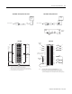
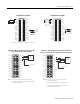
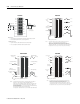
To L D T
1. This is a general wiring example illustrating Axis 1 wiring only. Other configurations are possible with Axis wiring identical to Axis 1.
2. Make sure that any transducer connected t othe 1756-HYD02 module uses an external interrogation signal.
3. Do exceed the specified isolation voltage between power sources.
NOTES:
General cable CO720 To E-stop relay coil
General cable CO720
General cable CO720
General cable CO722
General cable CO720
General cable CO721
To valve driver/amplifier
To hydraulic control unit
or
To valve or pump
To home
limit switch
To registration
sensor
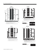
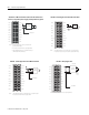
From 1756-HYD02
REG5V
IN_COM
5V dc
Field Power
Supply
+
5 Volt
Registration
Sensor
Supply
–
Output
Common
General cable
C0720
From 1756-HYD02
General cable
C0720
REG24V
IN_COM
24V dc
Field Power
Supply
+
24 Volt
Registration
Sensor
Supply
–
Output
Common
1756-HYD02 1756-HYD02 - Wiring 5V Sensors
1756-HYD02 - Wiring 24V Sensors