
User manual

1 Publication CIG-WD001B-EN-P - May 2005
Chapter
7
1756 ControlLogix I/O Modules
Shield
ground
Input
Device
Z0 12-24V dc
Z0 5V dc
Z0 Return
Customer VCC
F0
F0 Return
Not used
Not used
Output 0
Customer VCC
Z1 12-24V dc
Z1 5V dc
Z1 RET
Not used
Customer
Common
Not used
Output 1
F1
F1 Return
1.
NOTES:
12
3
4
5
6
78
9
10
1112
13
14
15
16
1718
1920
Customer
Common
+
–
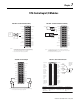
2. Do not connect more than 2 wires to any single terminal.
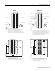
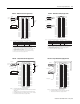
This wiring diagram can be used in applications with 50mV (magnetic pickup),
1.3V (TTL), and 4V (preamp level) thresholds. You must use RSLogix 5000 to
choose the appropriate threshhold level for your application.
Shield ground
Input
Device
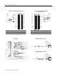
1. The wiring example above shows a 12-24V dc standard prover connected to the
module. If you use a 5V dc standard prover, make sure the positive wire is connected to
the 5V terminal (e.g. Z0 5V dc).
12
3
4
5
6
78
9
10
1112
13
14
15
16
1718
1920
+
–
Z0 12-24V dc
Z0 5V dc
Z0 Return
Customer VCC
F0
F0 Return
Not used
Not used
Output 0
Customer VCC
Z1 12-
24V dc
Z1 5V dc
Z1 RET
Not used
Customer
Common
Not used
Output 1
F1
F1 Return
Customer
Common
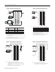
12-24V dc
NOTE:
+
–
Shield ground
2. Do not connect more than 2 wires to any terminal.
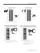
1756-CFM - Standard Flowmeter Wiring 1756-CFM - Standard Prover/Detector Wiring
NOTES:
12
3
4
5
6
78
9
10
1112
13
14
15
16
1718
1920
Load
+
–
Z0 12-24V dc
Z0 5V dc
Z0 Return
Customer VCC
F0
F0 Return
Not used
Not used
Output 0
Customer VCC
Z1 12-24V dc
Z1 5V dc
Z1 RET
Not used
Customer
Common
Not used
Output 1
F1
F1 Return
Customer
Common
Load
+
–
+
–
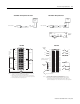
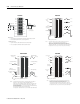
1. If separate power sources are used, do not exceed the specified isolation voltage.
2. Do not connect more than 2 wires to any single terminal.
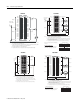
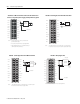
Appl ic ation : A1 Co nne cti ons: B 1 Co nne cti ons: Z1 Con nect ions :
Differential
Line Driver
Output (40mA)
White - A1 (5V)
Black of white - A1
(RET)
Blue - B1 (RET)
Black of blue - B1 (5V)
Green - Z1 (5V)
Black of green - Z1
(RET)
12
34
56
78
910
1112
1314
1516
1718
1920
2122
2324
2526
2728
2930
3132
3334
3536
Z1 (12-24V)
Z1 (5V)
Z1 (RET)
B1 (12-24V)
B1 (5V)
B1 (RET)
A1 (12-24V)
A1 (5V)
A1 (RET)
Not used
Not used
Not used
Z0 (12-24V)
Z0 (5V)
Z0 (RET)
B0 (12-24V)
B0 (5V)
B0 (RET)
A0 (12-24V)
A0 (5V)
A0 (RET)
Not used
Not used
Not used
COMMON 0
COMMON 0
COMMON 0
DC-0(+)
Out 2
Out 3
COMMON 1
COMMON 1
COMMON 1
DC-1(+)
Out 0
Out 1
Black
Black
White
Black
Blue
Green
Allen-Bradley
Bulletin 845
Incremental
Encoder
Differential Line
Driver Output
NOTE: Do not connect more than 2 wires to any single terminal.
1756-CFM - Standard Output 1756-HSC - 845 Incremental Encoder