
User manual

Publication CIG-WD001B-EN-P - May 2005
5-10 1746 I/O Modules
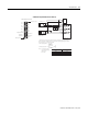
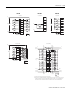
7-24V DC user power (1)
CW + or non directional pulse output (2)
CW - or non directional pulse output (3)
CW + pulse or direction signal output (4)
CCW - pulse or direction signal output (5)
External interrupt input (6)
Home limit switch input (7)
Home Proximity limit switch input (8)
CW limit switch input (9)
CCW limit switch input (10)
Pulse train enable/disable input (11)
A Hi (Loopback + non directional pulse) (12)
A Lo (Loopback - non directional pulse) (13)
B Hi (Loopback + direction) (14)
B Lo (Loopback - direction (15)
+ Encoder Marker (16)
- Encoder Marker (17)
0 V user power (DC common) (18)
A
1
1
1
+15 VDC
Return
A
B
Z
A
H
B
I
C
J
D
F
G
Case Ground
A-B 845H
Optical
Encoder
3
Z
B
Electrical Cabinet
Ground Bus
16 AWG
16 AWG
DC
SOURCE
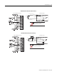
1. Use 3-pair, #22 gauge individually twisted and shielded pair, Belden 9504 or equivalent.
2. Use 1-pair, #18 gauge twisted and shielded cable.
3. Encoders must have +5V compatible differential line drive outputs on channels A, B and Z. (DS8830 or equivalent - Allen-Bradley 845H).
4. +15V from encoder power source - connect encoder return to 0V user power (DC common) at the power supply sources.
1746-HSTP1 – Wiring a 15V Encoder
A
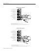
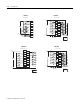
7-24V DC user power (1)
CW + or non directional pulse output (2)
CW - or non directional pulse output (3)
CW + pulse or direction signal output (4)
CCW - pulse or direction signal output (5)
External interrupt input (6)
Home limit switch input (7)
Home Proximity limit switch input (8)
CW limit switch input (9)
CCW limit switch input (10)
Pulse train enable/disable input (11)
A Hi (Loopback + non directional pulse) (12)
A Lo (Loopback - non directional pulse) (13)
B Hi (Loopback + direction) (14)
B Lo (Loopback - direction (15)
+ Encoder Marker (16)
- Encoder Marker (17)
0 V user power (DC common) (18)
1
1
1
+5V
Return
A
B
Z
A
H
B
I
C
J
D
F
G
Case Ground
A-B 845H
Optical
Encoder
3
DC
SOURCE
Z
B
Electrical Cabinet
Ground Bus
16 AWG
16 AWG
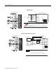
1. Use 3-pair, #22 gauge individually twisted and shielded pair, Belden 9504 or equivalent.
2. Use 1-pair, #18 gauge twisted and shielded cable.
3. Encoders must have +5V compatible differential line drive outputs on channels A, B and Z. (DS8830 or equivalent - Allen-Bradley 845H).
4. +5V from encoder power source - connect encoder return to 0V user power (DC common) at the power supply sources.
1746-HSTP1 – Wiring a 5V Encoder