
User manual

Publication CIG-WD001B-EN-P - May 2005
5-8 1746 I/O Modules
EXT PO WER
+5 V
RET
+15V
-/+RET
+2 4
+24R E T
EGND
- 15V
+5V
+5 V
+1 5V
+/- 15V
-15V
AC HI
AC LO
+2 4V
+24 V RE T
AC Line
+24V P ower Supply
L1
L2
COMM
COMM
Electrical Cabinet
Ground Bus
14 AWG
14 AWG (3)
14 AWG
14 AWG
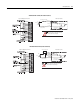
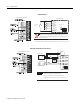
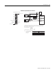
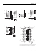
Wiring the power supply
1
Use three pair 22 gauge individually twisted and shielded cable.
2
Use one pair 18 gauge twisted and shielded cable.
3
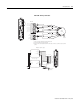
Encoders must have +5V compatible differential line drive outputs on channels A, B, and Z (DS 8830 or equivalent
(845H)).
CH A. HI
CH A. LO
AB SHLD
CH B. HI
CH B. LO
ZSHLD
CH Z. HI
CH Z. LO
+5 V
RET
+1 5 V
SHLD
A
H
I
B
C
J
D
F
G
Return
ENCODER
ENCODER POWER
3
1
1
1
2
A
B
Z
A
B
Z
+15V
+15V
Case
Ground
Optical
Encoder
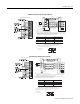
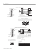
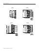
1746-HSRV – Wiring a 15V Encoder