
User manual

Publication CIG-WD001B-EN-P - May 2005
1746 I/O Modules 5-7
VS
A(+)
A(–)
B(+)
B(–)
Z(+)
Z(–)
+VDC
COM
VS
OUT
COM
OUT
COM
VS
OUT
COM
R
(1)
Power
S uppl y
photoelectric sensor
with open collector
sinking output
proximity sensor
solid-state
switch
5V dc 127 W
12V dc 238 W
24V dc 2140 W
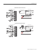
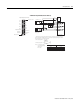
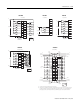
Module Inputs
1. External resistors are needed if not internal to the encoder. The pull-up resistor (R) value depends on
the power supply value. The table below shows resistor values for typical supply voltages. To calculate
the resistor value, use one of the following formulas:
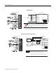
For 5V dc jumper position: R =
(V
cc
- V
min
)
I
min
For 24V dc jumper position: R =
(V
cc
- V
min
)
I
min
- 1KΩ
[
[
where: R = pull-up resistor value
V
cc
= power supply voltage
V
min
= 4.2V dc
I
min
= 6.3mA
Power Supply Voltage (V
cc
)
Pull-up Resistor Value (R)
1
1 Resistance values may change, depending upon your application.
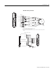
B1-
A1 -
A2-
Z1-
Z2-
B2 -
OUTPUT 0
+V dc
B1 +
A1 +
A2 +
Z1+
Z2+
B2 +
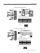
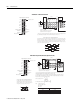
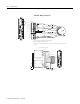
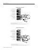
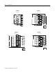
Input and Output Connections
OUTPUT 2
Release screw
Release screw
Output common
OUTPUT 1
OUTPUT 3
1746-HSCE2 Single-Ended (Discrete Devices)