
User manual

Publication CIG-WD001B-EN-P - May 2005
5-6 1746 I/O Modules
B1-
A1 -
A2-
Z1-
Z2-
B2 -
OUTPUT 0
+V dc
B1 +
A1 +
A2 +
Z1+
Z2+
B2 +
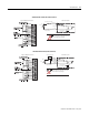
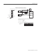
Input and Output Connections
OUTPUT 2
Release screw
Release screw
Output common
OUTPUT 1
OUTPUT 3
A
A
B
B
Z
Z
A(+)
A(–)
B(+)
B(–)
Z(+)
Z(–)
GND
VS
+VDC
COM
Cabl e
(1)
Power
S upply
Shi eld
E arth
A
A
B
B
Z
Z
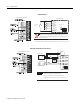
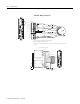
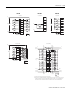
Differential Encoder Output Waveforms
The figure below shows the different encoder output waveforms. If your encoder matches these
waveforms, the encoder signals can be directly connected to the associated screw terminals on
the module. For example, the A lead from the encoder is connected to the module’s A+ screw.
If your encoder does not match these waveforms, some wiring modifications may be necessary.
See the user’s manual for your encoder.
1 Refer to your encoder manual for proper cable type. The type of cable used should be twisted
pair, individually shielded cable with a maximum length of 300m (1000 ft.).
Allen-Bradley
845H Series
differential
encoder
Module Inputs
shield/housing
Connect only if housing is electronically
isolated from the motor and ground.
1746-HSCE2 – Differential Encoder
B1-
A1 -
A2-
Z1-
Z2-
B2 -
OUTPUT 0
+V dc
B1 +
A1 +
A2 +
Z1+
Z2+
B2 +
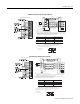
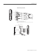
Input and Output Connections
OUTPUT 2
Release screw
Release screw
Output common
OUTPUT 1
OUTPUT 3
5V dc 127 W
12V dc 238 W
24V dc 2140 W
A
B
Z
A(+)
A(–)
B(+)
B(–)
Z(+)
Z(–)
GND
VS
+VDC
COM
R
(2)
P o wer
Su ppl y
Earth
cab le
(1 )
shi eld
A
B
Z
Allen-Bradley
845H Series
differential
encoder
Module Inputs
shield/housing
Connect only if housing is electronically
isolated from the motor and ground.
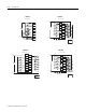
1. Refer to your encoder manual for proper cable type. The type of cable used should be twisted pair,
individually shielded cable with a maximum length of 300m (1000 ft.).(2)
2. External resistors are needed if not internal to the encoder. The pull-up resistor (R) value depends on
the power supply value. The table below shows resistor values for typical supply voltages. To calculate
the resistor value, use one of the following formulas:
For 5V dc jumper position: R =
(V
cc
- V
min
)
I
min
For 24V dc jumper position: R =
(V
cc
- V
min
)
I
min
- 1KΩ
[
[
where: R = pull-up resistor value
V
cc
= power supply voltage
V
min
= 4.2V dc
I
min
= 6.3mA
Power Supply Voltage (V
cc
)
Pull-up Resistor Value (R)
1
1 Resistance values may change, depending upon your application.
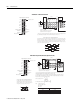
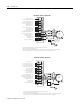
Single-Ended Encoder Output Waveforms
The figure below shows the single-ended encoder
output waveforms. When the waveform is low, the
encoder output transistor is on. When the waveform
is high, the encoder output transistor is off.
1746-HSCE2 Single-Ended Encoder (Open-Collector)