
User manual

Publication CIG-WD001B-EN-P - May 2005
1746 I/O Modules 5-5
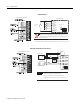
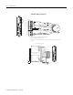
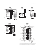
VS V alue R Value Max imu m Outpu t Leak age
+5V dc 150 ohm 1/4W 5% 6.3 mA
+12V dc 1800 ohm 1/4W 5% 1.5 mA
+24V dc 4700 ohm 1/4W 5% 1.2 mA
A
B
Z
A(+)
A(-)
B(+)
B(-)
Z(+)
Z(-)
R
1 2 3
4
+VDC
CO M
VS
GN D
Belden 9503 or equivalent
305m (1000tft) max length
Power
Supply
Earth
Shield
(2)
SW1
ON
OF F
(All switches OFF)
cable
(1)
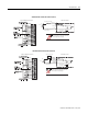
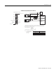
(1) Refer to your encoder manual for proper cable type and length.
(2) Due to the topology of the module’s input circuits, terminating the shield at the encoder end provides the highest immunity
to EMI interference. Connect EARTH ground directly to the encoder connector housing.
(3) The pullup resistor (R) value depends on the power supply value (VS). The table below lists the resistor values for typical
power supply values. These resistors must be located at the encoder end of the cable.
(3)
A
B
Z
low = transistor ON
high = transistor OFF
Input and Output Connections
Allen-Bradley
845H Series
differential
encoder
Module Inputs
encoder connector
housing
Single-Ended Encoder Output Waveforms
The figure below shows the single-ended output waveforms. When the waveform
is low, the encoder output transistor is ON.
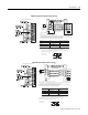
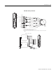
1746-HSCE Single-Ended Encoder (Open-Collector)
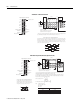
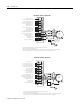
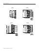
VS Value R Value Max imu m Outpu t Leak age
+5V dc no resistor needed 6.3 µA
+12V dc 1800 ohm 1/4W 5% 1.5 µA
+24V dc 4700 ohm 1/4W 5% 1.2 µA
R
R
A
Z
A(+)
A(-)
B(+)
B(-)
Z(+)
Z(-)
B
12 34
R
+VDC
COM
VS
GND
Belden 9503 or equivalent
305m (1000tft) max length
Power
Supply
Shield
(2)
Module Inputs
SW1
ON
OFF
(All switches OFF)
cable
(1)
single ended
encoder
(4)
(1) Refer to your encoder manual for proper cable type and length.
(2) Due to the topology of the module’s input circuits, terminating the shield at the encoder end provides the highest immunity
to EMI interference. Connect EARTH ground directly to the encoder connector housing.
(3) The resistor (R) value depends on the power supply value (VS). The table below lists the resistor values for typical power
supply values. These resistors must be located at the encoder end of the cable.
(4) The Allen-Bradley 845H sourcing encoder is not compatible with this module.
(3)
(3)
(3)
Earth
A
B
Z
low = transistor OFF
high = transistor ON
Single-Ended Encoder Output Waveforms (Sourcing)
The figure below shows the single-ended encoder output waveforms. When the
waveform is low, the encoder output transistor is OFF.
Input and Output Connections
1746-HSCE Single-Ended Encoder (Sourcing)