
User manual

Publication CIG-WD001B-EN-P - May 2005
5-4 1746 I/O Modules
+
-
1 234
User Supplied
24V dc
wiring terminals
DC COM
All switches OFF
ON
OFF
Dip Switch SW2
OUT 3
OUT 2
OUT 1
OUT 0
VDC
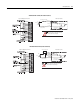
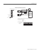
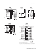
Input and Output Connections
1746-HSCE module
Do not use incandescent lamps as output indicators. The high peak inrush current
required to heat the filament can damage the module’s output circuits. Use LED
type indicators that satisfy the output circuit ratings, such as Allen-Bradley 800A
and 800T LED indicators.
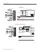
The outputs are not electrically isolated from each other. (They are referenced to the same output
common terminal.) However, outputs are isolated from the rest of the circuitry to a level of 1500 volts.
1746-HSCE Outputs
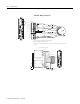
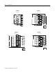
Input and Output Connections
IMPORTA NT
1 2 34
A(+)
A(-)
B(+)
B(-)
Z(+)
Z(-)
R1
R2
VS
OU T
CO M
VS
OU T
CO M
VS
OU T
CO M
+V DC
CO M
proximity sensor with
photoelectric sensor with open
solid-state
switch
(5V output)
Power
Supply
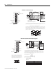
Module Inputs
SW1
ON
OF F
(All switches OFF)
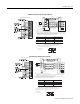
This diagram shows the sensors operation from a common power supply.
Separate power supplies for each circuit can be used.
The resistor (R1) value depends on the power supply value (VS).
The pullup resistor (R2) value depends on the power supply value (VS).
1746-HSCE Single-Ended (Discrete Devices)