
User manual

Publication CIG-WD001B-EN-P - May 2005
1738 ArmorPoint 4-5
3
4
5
6
7
8
9
10
10
11
11
12
12
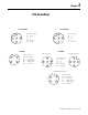
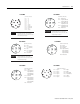
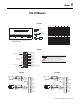
2
1
Pin 1 +A
Pin 2 ~A
Pin 3 +B
Pin 4 ~B
Pin 5 +Z
Pin 6 ~Z
Pin 7 Chassis
Pin 8 Chassis
Pin 9 Return (Com)
Pin 10 Return (Com)
Pin 11 5V dc
Pin 12 Chassis
IMPORTANT
Analog and specialty modules have earth
grounded metal rings. This should be
considered when choosing shielded cables
and grounding techniques.
(view into connector)
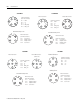
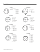
Pin 1 No Connect
Pin 2 Input 0A (M12-A)
Input 1A (M12-B)
Pin 3 Input 0C (M12-A)
Input 1C (M12-B)
Pin 4 Input 0B (M12-A)
Input 1B (M12-B)
Pin 5 No Connect
IMPORTANT
Analog and specialty modules have earth
grounded metal rings. This should be
considered when choosing shielded cables
and grounding techniques.
(view into connector)
1738-IJM23 1738-IR2M12
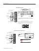
(view into connector)
Pin 1 24V dc
Pin 2 No Connect
Pin 3 Common
Pin 4 Input 0 (M12-A)
Input 1 (M12-B)
Input 2 (M12-C)
Input 3 (M12-D)
Pin 5 No Connect
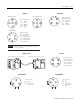
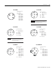
Pin 1 CJC +
Pin 2 TC 0 + (M12-A
)
TC 1 + (M12-B)
Pin 3 CJC -
Pin 4 TC 0 - (M12-A
)
TC 1 - (M12-B)
Pin 5 No Connect
IMPORTANT
Analog and specialty modules have earth
grounded metal rings. This should be
considered when choosing shielded cables
and grounding techniques.
(view into connector)
1738-IT2IM12 1738-IV4M12
(view into connector)
Pin 1 24V dc
Pin 2 Input 1 (M12-A)
Pin 4 Input 0 (M12-A)
Input 3 (M12-B)
Input 2 (M12-B)
Input 5 (M12-C)
Input 4 (M12-C)
Input 7 (M12-D)
Input 6 (M12-D)
Pin 3 Common
Pin 5 No Connect
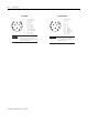
3
4
5
6
7
8
9
10
11
12
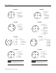
2
1
(view into connector)
Pin 1 Input 0 Pin 7 Input 6
Pin 2 Input 1 Pin 8 Input 7
Pin 3 Input 2 Pin 9 Return (Com)
Pin 4 Input 3 Pin 10 Return (Com)
Pin 5 Input 4 Pin 11 24V dc
Pin 6 Input 5 Pin 12 Chassis
1738-IV8M12 1738-IV8M23