
User manual

Publication CIG-WD001B-EN-P - May 2005
1738 ArmorPoint 4-3
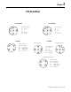
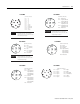
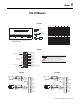
Male Auxiliary
Male In Connector
(view into connector)
Pin 1 +5VBUS
Pin 2 A-Line
Pin 3 GNDBUS
Pin 4 B-Line!
Pin 5 Shield
Female In Connector
((view into connector)
Pin 1 User Power -
Pin 2 Adapter Power -
Pin 3 Protective GND
Pin 4 Adapter Power +
Pin 5 User Power +
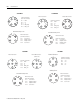
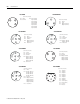
Male In connector
IMPORTANT
Profibus Adapter Network connections have earth grounded metal
rings. This should be considered when choosing shielded cables
and grounding techniques.
(view into connector)
Pin 1 User Power +
Pin 2 Adapter +
Pin 3 Adapter -
Pin 4 User Power -
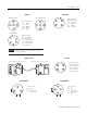
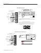
Male In Connector
1738-APB 1738-EP24DC
Module will bridge the extension unit and the base
Module will bridge the extension unit and the base
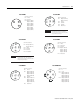
(view into connector)
Pin 1 User Power +
Pin 2 No Connect
Pin 3 No Connect
Pin 4 User Power -
Male In Connector
1738-EXT1, -EXT3 1738-FPD
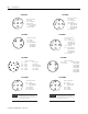
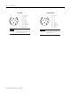
(view into connector)
Pin 1 Chassis
Pin 2 L1
Pin 3 Input 0 (M12-A)
Input 1 (M12-B)
(view into connector)
Pin 1 L1
Pin 2 L2/N
Pin 3 Input 0 (M12-A)
Input 1 (M12-B)
Pin 4 Chassis
1738-IA2M12AC3 1738-IA2M12AC4