
User manual


Publication CIG-WD001B-EN-P - May 2005
21-2 1798 FLEX Armor I/O Modules
2
1
1
2
4
3
3
4
5
5
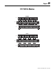
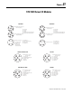
Male M12 Connector
(PBUS IN)
Female M12 Connector
(PBUS OUT)
Pin 1 +5V BUS
Pin 2 A-Line
Pin 3 GNDBUS
Pin 4 B-Line
Pin 5 Shield
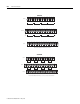
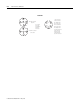
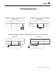
Power Connector
(Male Connector)
Pin 1 Output Power -
Pin 2 Sensor Power -
Pin 3 Protective Gnd
Pin 4 Sensor Power +
Pin 5 Output Power +
5
4
2
1
3
The connection to the
power connector
should be a 5-pin
female mini quick
disconnect connector.
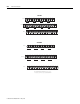
1798-PFTP1