
User manual


Publication CIG-WD001B-EN-P - May 2005
19-22 1794 FLEX I/O Modules
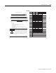
0 A-0 C-35 8 A-8 C-43
1 A-1 C-36 9 A-9 C-44
2 A-2 C-37 10 A-10 C-45
3 A-3 C-38 11 A-11 C-46
4 A-4 C-39 12 A-12 C-47
5 A-5 C-40 13 A-13 C-48
6 A-6 C-41 14 A-14 C-49
7 A-7 C-42 15 A-15 C-50
Common B-16 through B-33 +V dc C-34 through C-51
0 1 2 3 4 5 6 7 8 9 10 11 12 13 14 15
1716 18 19 20 21 22 23 24 25 26 27 28 29 30 31 32
33
34 35 36 37 38 39 40 41 42 43 44 45 46 47 48 49
51
50
0 1 2 3 4 5 6 7 8 9 10 11 12 13 14 15
0-15
16-33
34-51
A
B
C
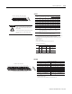
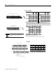
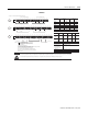
1794-TB3, -TB3K, -TB3S
Output
Channel
Output
Channel
Output
Terminal
Power
Terminal
Output
Terminal
Power
Terminal
Connect +V to C-34.
Connect +V common to B-16.
Use B-33 and C-51 for daisy chaining to the next terminal base unit.
1794-TB3, -TB3K, -TB3S
1794-OV16, 1794-OV16P
A-1
16 0 2 4 6 8 1 0 1 2 14 33
34 13 57911131551
0 1 2 3 4 5 6 7 8 9 10 11 12 13 14 15
1716 18 19 20 21 22 23 24 25 26 27 28 29 30 31 32
33
34 35 36 37 38 39 40 41 42 43 44 45 46 47 48 49
51
50
16 33
34 51
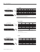
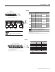
Even Numbered Terminals 0 through 14
Odd Numbered Terminals 1 through 15
16, 0, 2, 4, 6,
8. 10. 12. 14. 33
34, 1, 3, 5, 7,
9, 11, 13, 15, 51
B
C
B
C
A
0-15
16-33
34-51
1794-TBN, -TBNK, -TBNF
1794-TB2, -TB3, -TB3K, -TB3, -TB3S
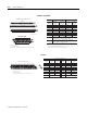
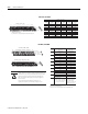
!
Do not attempt to increase load current or wattage capability beyond the maximum
rating by connecting 2 or more outputs in parallel. The slightest variation in relay
switching time may cause one relay to momentarily switch the total load current.
Apply only +24V dc power to the power terminals on the terminal base unit.
Make certain that all relay wiring is properly connected before applying any
power to the module.
Total current draw through the terminal base unit is limited to 10A.
Separate power connections to the terminal base unit may be necessary.
ATTENTION
0
A-0
1794-TB2, -TB3,
-TB3K, -TB3S
Output Terminal
1794-TBN,
-TBNK, -TBNF
Output Terminal
A-3
1
A-2
A-5
2
A-4
A-7
3
A-6
C-1
B-0
C-3
B-2
C-5
B-4
C-7
B-6
Output
Channel
A-9
4
A-8
A-11
5
A-10
A-13
6
A-12
A-15
7
A-14
C-9
B-8
C-11
B-10
C-13
B-12
C-15
B-14
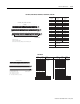
A = output terminals
B = dc common terminals
C = power terminals (C-34 through
C-51 for 1794-TB3, -TB3K -TB3S;
C-34 and C-51 for 1794-TB2)
B = even numbered output
terminals 0-14, 24V dc common
terminals 8-16 and B-33
C = odd numbered output
terminals 1-15; 24V dc power
terminals C-34 and C-51
Terminals 35 and 50 are not used on 1794-TB2
Connect +24V dc to C-34.
Connect +24V dc common to B-16.
Use B-33 and C-51 for daisy chaining to the next terminal base unit.
1794-OW8, 1794-OW8K