
User manual


Publication CIG-WD001B-EN-P - May 2005
1794 FLEX I/O Modules 19-21
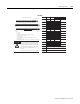
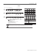
Signal Type La bel Ma rkings Terminal Shiel d (TB3T/TB 3TS) Termi nal
0
Current Output I0 A-0
C-39
B-0
Current Return I0 Ret A-1 C-1
Voltage Output V0 A-2
C-40
B-2
Voltage Return V0 Ret A-3 C-3
1
Current Output I1 A-4
C-41
B-4
Current Return I1 Ret A-5 C-5
Voltage Output V1 A-6
C-42
B-6
Voltage Return V1 Ret A-7 C-7
2
Current Output I2 A-8
C-43
B-8
Current Return I2 Ret A-9 C-9
Voltage Output V2 A-10
C-44
B-10
Voltage Return V2 Ret A-11 C-11
3
Current Output I3 A-12
C-45
B-12
Current Return I3 Ret A-13 C-13
Voltage Output V3 A-14
C-46
B-14
Voltage Return V3 Ret A-15 C-15
Common
TB2, TB3, TB3K, TB3S: Terminals 16 through 33 are internally connected in the terminal base unit
TB3T, TB3TS: Terminals 16, 17, 19, 21, 23, 25, 27, 29, 31, and 33 are internally connected in the terminal base unit
TBN, TBNK: Terminals 16 and 33 are internally connected in the terminal base unit
TB2, TBN, TBNK: Terminals 34 and 51 are internally connected in the terminal base unit
TB3, TB3K, TB3S: Terminals 34 through 51 are internally connected in the terminal base unit
TB3T, TB3TS: Terminals 34, 35, 50, and 51 are internally connected in the terminal base unit
Chassis Gnd
TB3T, TB3TS: Terminals 39 through 46 are internally connected to chassis gnd
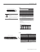
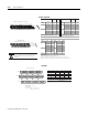
16 0 2 4 6 8 1 0 1 2 1 4 3 3
34 1 3 5 7 9 11 13 15 51
16 33
34 51
Even Numbered Terminals 0 through 14
Odd Numbered Terminals 1 through 15
16, 0, 2, 4, 6,
8. 10. 12. 14. 33
34, 1, 3, 5, 7,
9, 11, 13, 15, 51
B
C
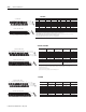
0 1 2 3 4 5 6 7 8 9 10 11 12 13 14 15
Current
Output
Device
A
B
C
34-51
16-33
0-15
I
+-
-+
+
II I
+
-
-
-
+
+
+
ac or dc
4-Wire Output
Device
dc only
3-Wire Output
Device
Current Only
2-Wire Output
Device
dc only
3-Wire Output
Device
IRVRIRVRIRVRIRVR
Current
Output
Device
Current
Output
Device
Voltage
Output
Device
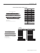
34 and 51
for T B2
1794-TBN, -TBNK
1794-TB2, -TB3, -TB3K, -TB3S, -TB3T, -TB3TS
+V dc
Output
Channel
Connect +V to C-34.
Connect +V common to B-16.
Use B-33 and C-51 for daisy chaining to the next terminal base unit.
Connect any signal wiring shield to functional ground as near as possible to the module when
using the 1794-TB2, -TB3, -TB3K, -TB3S, -TBN or -TBNK. With the 1794-TB3T and -TB3TS, use terminals C-39 through C-46.
!
Only connect either a voltage signal or a current signal per channel, not both.
To reduce susceptibility to noise, power analog and digital modules from
separate power supplies. Do not exceed a length of 3M (9.8 ft) for DC
power cabling.
ATTENTION
1794-TBN, -TBNK1794-TB2, -TB3, -TB3K, -TB3S, -TB3T, -TB3TS
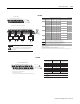
1794-OF4I
Output Ch annel
Output Termin al
Common Terminal
1
0B-0
1B-2
2B-4
3B-6
4B-8
5B-10
6B-12
7B-14
B = even numbered output terminals 0 through 14, ac common terminals 16 and 33
C = power terminals C-34 and C-51, and odd numbered output common terminals 1
through 15
1. C-1, 3, 5, 7, 9, 11, 13, and 15 are internally connected in the module to 220V ac
common L2.
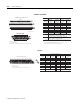
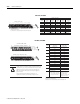
16 0 2 4 6 8 1 0 1 2 14 33
34 13 57911131551
16
34 51
Even Numbered Terminals 0 through 14
Odd Numbered Terminals 1 through 15
16, 0, 2, 4, 6,
8. 10. 12. 14. 33
34, 1, 3, 5, 7,
9, 11, 13, 15, 51
B
C
33
1794-TBN, -TBNK, -TBNF
Connect 220V ac L2 common to B-16.
Connect 220V ac L1 to C-34.
Use B-33 and C-51 for daisy chaining to the next terminal base unit.
C-1
C-15
C-13
C-11
C-9
C-7
C-5
C-3
1794-TBN, -TBNK, -TBNF
1794-OM8