
User manual


Publication CIG-WD001B-EN-P - May 2005
19-20 1794 FLEX I/O Modules
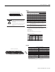
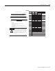
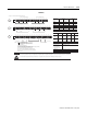
TB 3T, TB 3TS TB 3T, TB 3TS
Signal Type Output
Terminal
Shield Signal Type Input
Termi nal
Shie ld
0
Current Signal A-0 C-39
2
Current Signal A-8 C-43
Current Common
A-1
1
C-39 Current Common
A-9
1
C-43
Voltage Signal A-2 C-40 Voltage Signal A-10 C-44
Voltage Common
A-3
1
C-40 Voltage Common
A-11
1
C-44
1
Current Signal A-4 C-41
3
Current Signal A-12 C-45
Current Common
A-5
1
C-41 Current Common
A-13
1
C-45
Voltage Signal A-6 C-42 Voltage Signal A-14 C-46
Voltage Common
A-7
1
C-42 Voltage Common
A-15
1
C-46
Common for TB2, TB3, TB3K, TB3S: B-16 through B-33
Common for TB3T and TB3TS: B-16, 17, 19, 21, 23, 25, 27, 29, 31, and 33
V dc Power for TB2: C-34 and C-51
V dc Power for TB3T and TB3TS: C-34, 35, 50, and 51
1 A-1, 3, 5, 7, 9, 11, 13, and 15 are internally connected in the module to +V common.
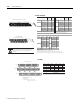
0 1 2 3 4 5 6 7 8 9 10 11 12 13 14 15
1716 18 19 20 21 22 23 24 25 26 27 28 29 30 31 32
33
34 35 36 37 38 39 40 41 42 43 44 45 46 47 48 49
51
50
0 1 2 3 4 5 6 7 8 9 10 11 12 13 14 15
0-15
16-33
34-51
A
B
C
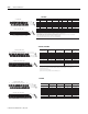
Signal
Type
Output
Terminal
Output
Terminal
0 Current Signal B-0 2 Current Signal B-8
Current Common C-1 Current Common C-9
Voltage Signal B-2 Voltage Signal B-10
Voltage Common C-3 Voltage Common C-11
1 Current Signal B-4 3 Current Signal B-12
Current Common C-5 Current Common C-13
Voltage Signal B-6 Voltage Signal B-14
Voltage Common C-7 Voltage Common C-15
Common
B-16 and B-33
V dc
C34 and C-51
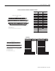
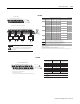
16 0 2 4 6 8 1 0 1 2 14 3 3
34 13 57911131551
16, 0, 2, 4, 6,
8, 10, 12, 14, 33
34, 1, 3, 5, 7,
9, 11, 13, 15, 51
B
C
16 33
34 51
Even Numbered Terminals 0 through 14
Odd Numbered Terminals 1 through 15
1794-TBN and -TBNK
1794-TB2, -TB3, -TB3K, -TB3S, -TB3T, -TB3TS
+
+
+ Vdc Power for TB3, TB3K and TB3S: C-34 through C-51
+
Terminals 35 and 50 are not used on 1794-TB2
Output
Channel
Output
Channel
Output
Channel
Output
Channel
Connect +V to C-34.
Connect +V common to B-16.
Use B-33 and C-51 for daisy chaining to the next terminal base unit.
Connect any signal wiring shield to functional ground as near as possible to the module when using the
1794-TB2, -TB3, -TB3K -TB3S, -TBN or -TBNK. With the 1794-TB3T and -TB3TS, use terminals C-39 through C-46.
!
ATTENTION
Signal
Type
Only connect either a voltage signal or a current signal per channel, not both.
To reduce susceptibility to noise, power analog and digital modules from
separate power supplies. Do not exceed a length of 3M (9.8 ft) for DC
power cabling.
TB2, TB3,
TB3K, TB3S,
TB3T, TB3TS
TB2, TB3,
TB3K, TB3S,
TB3T, TB3TS
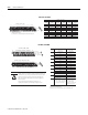
1794-OE4, 1794-OE4K
Row A
Row B
Row C
ch0
ch1 ch2 ch3
+V +V-V -V
0 1 2 3 4 5 6 7 8 9 10 11 12 13 14 15
16 17 18 19 20 21 22 23 24 25 26 27 28 29 30 31 32 33
34 35 36 37 38 39 40 41 42 43 44 45 46 47 48 49 50 51
++++----
ch4 ch5 ch6
ch7
+- + - +- +-
1794-TB3G, -TB3GK, -TB3GS
Ou tput Output + Output - Output Output + Output -
Output 0 A-0 A-1 Output 4 B-17 B-18
Output 1 A-4 A-5 Output 5 B-21 B-22
Output 2 A-8 A-9 Output 6 B-25 B-26
Output 3 A-12 A-13 Output 7 B-29 B-30
+V
-V
Terminals 34 and 50
Terminals 35 and 51
+24V dc = Terminals C-34 and C-50
-V = C-35 and C-51
For daisy-chaining: Supply in - C-34 (+) and C-35 (-)
Supply out - C-50 (+) and C-51 (-)
NC = No connection
1794-OE8H