
User manual

Publication CIG-WD001B-EN-P - May 2005
19-14 1794 FLEX I/O Modules
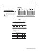
Signal
Ret urn
1
0 A-0 A-1 B-17 B-18
1 A-2 A-3 B-19 B-20
2 A-4 A-5 B-21 B-22
3 A-6 A-7 B-23 B-24
4 A-8 A-9 B-25 B-26
5 A-10 A-11 B-27 B-28
6 A-12 A-13 B-29 B-30
7 A-14 A-15 B-31 B-32
Common
+V dc
C-39
C-40
C-41
C-42
C-43
C-44
C-45
C-46
01 234 56 78 9101112131415
17 18 19 20 21 22 23 24 25 26 27 28 29 30 31 32
33
16
34 35 36 37 38 39 40 41 42 43 44 45 46 47 48 49
51
50
1794-TB2, -TB3, -TB3K, -TB3S, -TB3T, -TB3TS
0 1 2 3 4 5 6 7 8 9 10 1112 1314 15
0-15
16-33
A
B
C
!
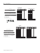
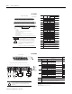
To reduce the susceptibility to noise, power analog
modules and digital modules from separate power
supplies. Do not exceed a length of 3m (9.8ft) for dc
power cabling.
Do not daisy chain power or ground from the RTD
terminal base unit to any ac or dc digital module
terminal base unit.
ATTENTION
Use the following Belden cables for connecting the
RTD to the terminal base unit.
9501
9533
8350 3
1 Greater than 55% for more than 8 hours
RTD Type
2-wire
Length of Run/Humidity Level
Belden Cable
Number
3-wire
Not applicable
Less than 100 ft (30.5m)
with normal humidity
Over 100 ft (30.5m) or
high humidity
1
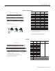
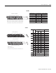
Channel High Signal Low Signal
Shield Return
TB2, TB3, TB3S TB3T, TB3TS
B-16 through B-33 for 1794-TB2, -TB3, -TB3K and -TB3S
B-16, B-17, B-19, B-21, B-23, B-25, B-27, B-29, B-31 and B-33 for 1794-TB3T and -TB3TS
C-34 through C-51 for 1794-TB3, -TB3K and -TB3S; C-34 and C-51 for 1794-TB2
C-34, C-35, C-50 and C-51 for 1794-TB3T and -TB3TS
1. When using a 2-wire RTD, jumper the signal return to the low signal terminal.
2. B-18, B-20, B-22, B-24, B-26, B-28, B-30 and B-32 are tied to Common on 1794-TB2, -TB3, -TB3K, -TB3S;
C-39 through C-46 are tied to chassis ground on 1794-TB3T and 1794-TB3ST
Terminals 35 through 50 are not used on the 1794-TB2
Connect +V to C-34
Connect +V common to B-16
Use B-33 and C-51 for daisy chaining to the next terminal base unit
34-51
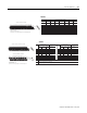
1794-IR8
0 1 2 3 4 5 6 7 8 9 10 11 12 13 14 15
16 17 18 19 20 21 22 23 24 25 26 27 28 29 30 31 32 33
34 35 36 37 38 39 40 41 42 43 44 45 46 47 48 49 50 51
+HL-+HL-+HL-+HL-
+HL-+HL-+HL-+HL-
Chassis Gnd Chassis Gnd
Channel 0 Channel 1 Channel 2 Channel 3
Channel 4 Channel 5 Channel 6 Channel 7
+V COM 6 Chassis Ground
for Shields
+V COM
24V dc
Supply In
24V dc
Supply Out
CJC
0-15
16-33
34-51
A
B
C
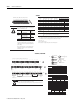
Ty pe of Input
Connect the following
HL + -
Sh ie ld
1
RTD - 2-wire 1 2
RTD - 3-wire 3 1 2
RTD - 4-wire 1a 2a 1 2
Thermocouple 1 2
Millivolt 1 2
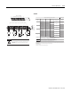
1
RTD or
Ther mocouple
Channel
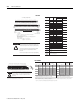
1794-TB3G, -TB3GK and -TB3GS Terminal Base Units
High Signal
Te r m
in al (H)
Low Signal
Terminal (L
)
RTD Source
Cu rre nt
(+)
Signal
Return
(-)
0 A-1 A-2 A-0 A-3
1 A-5 A-6 A-4 A-7
2 A-9 A-10 A-8 A-11
3 A-13 A-14 A-12 A-15
4 B-18 B-19 B-17 B-20
5 B-22 B-23 B-21 B-24
6 B-26 B-27 B-25 B-28
7 B-30 B-31 B-29 B-32
+V dc
C-34 and 50 - Connect +V to C-34
Common
RTD Thermocouple
Millivolt
2-Wire
3-Wire
1
2
3
1
2
1
1a
2a
2
1
2
1
2
+
mV
-
4-Wire
!
To reduce the susceptibility to noise, power analog modules and digital modules from separate power
supplies. Do not exceed a length of 3m (9.8ft) for dc power cabling.
Do not daisy chain power or ground from this module to any ac or dc digital module terminal base unit.
ATTENTION
Connections for 1794-TB3G, -TB3GK and -TB3GS (TB3G shown)
Terminals B-16, B-33 and C-40 through C-45 are Chassis Gnd for signal wire shields.
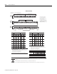
Input
CJC Sensor
+
_
Chassis Ground CJC Tail
CJC1 37 38 39 5 (22)
CJC2 46 47 48 12 (29)
1 - Use pins 5 and 12 when channels 0-7 are configured as thermocouples. Use pins 12 and
29 when only channels 4-7 are configured as thermocouples.
1
NC NC
NC = No connect
Chassis
GND
CJC
Chassis
GND
C-35 and 51 - Connect +V common to C-35
1794-IRT8, 1794-IRT8K