
User manual


Publication CIG-WD001B-EN-P - May 2005
3-2 1734D POINTBlock I/O Modules
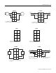
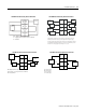
V ac
NC
NC
L2in
L1in
120V ac
Power
NC = No connection
L2/N = AC Return/Neutral L1 = AC Power
NC
NC
0
2
L2
L1
1
3
L2
L1
4
6
L2
L1
5
7
L2
L1
0A
0B
2A
2B
1A
1B
3A
3B
4A
4B
6A
6B
5A
5B
7A
7B
Field Power
Inputs Outputs
L1in
L2in
This supply will be connected to the internal power bus.
RTB 0 RTB 1 RTB 2 RTB 3 RTB 4
01
23
45
67
01
23
45
67
01
23
45
67
01
23
45
67
01
23
45
67
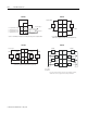
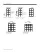
Load
Out 0 Out 1
2
L2
L2
L2
L2
3
Load
L1 = 120V ac
L2 = Return
3
5
7
01
2
4
6
Out Out
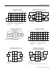
1734D-IA8XOA8, -IA8XOA8S Output 1734D-IA8XOW8, -IA8XOW8S
Prox
In 0 In 1
In 2
L2
L1 L1
L2
In 3
Prox
L1 = 120V ac
L2 = Return
3
5
7
01
2
4
6
2-Wire 3-Wire
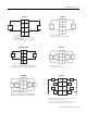
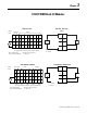
Out 0A
Out 0B
Out 1A
Out 1B
Load
Power
Supply
Out = Output channel relay contacts
L1 = 120V ac
L2 = Return
0
2
4
6
3
5
7
1
Power
Supply
Load
Out 2A
Out 2B
Out 3A
Out 3B
NOTE: This module cannot be powered by an internal power load.
1734D-IA8XOW8, -IA8XOW8S Input 1734D-IA8XOW8, -IA8XOW8S Output
(Load Powered by External Power)
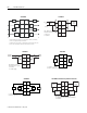
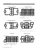
V ac
NC
NC
C
Vin
12/24V dc
Power
NC = No Connection Chas Gnd = Chassis Ground
C = Common V = Supply
NC
NC
0
2
C
V
1
3
C
V
4
6
C
V
5
7
C
V
8
10
C
V
9
11
C
V
12
14
C
V
13
15
C
V
Field Power
Inputs
Vin
C
This supply will be connected to the internal power bus.
RTB 0 RTB 1 RTB 2 RTB 3 RTB 4
01
23
45
67
01
23
45
67
01
23
45
67
01
23
45
67
01
23
45
67
Prox
In 0 In 1
In 2
C
VV
C
In 3
Prox ProxProx
V = 12/24V dc
C = Common
3
5
7
01
2
4
6
RTB 1
Repeat for RTB 2, 3, and 4
2-Wire 3-Wire 2-Wire3-Wire
1734D-IB16, -IB16S 1734D-IB16, -IB16S Sink Input