
User manual

Publication CIG-WD001B-EN-P - May 2005
19-12 1794 FLEX I/O Modules
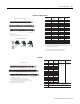
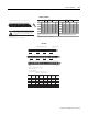
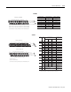
0 1 2 3 4 5 6 7 8 9 10 11 12 13 14 15
16 17 18 19 20 21 22 23 24 25 26 27 28 29 30 31 32 33
34 35 36 37 38 39 40 41 42 43 44 45 46 47 48 49 50 51
3V 6V 24V
Pwr
RET 50
mV
Sel
500/50
mV
F24V
Pwr
24V
Pwr
F 500/50
mV
50
mV
Sel
RET 24V
Pwr
6V 3V
Out 0 Out 0
Ret
RET 50
mV
Sel
500/50
mV
G24V
Pwr
24V
Pwr
G 500/50
mV
50
mV
Sel
RET Out 1 Out 1
Ret
Chassis Gnd Chassis Gnd
Channel 0 Frequency Input Channel 1 Frequency Input
Channel 0 Gate Input
Channel 1 Gate Input
+V COM
Gnd
6 Chassis Ground
for Shields
+V COM
24V dc
Supply In
24V dc
Supply Out
Channel 0 Output Supply Channel 1 Output Supply
Sply
0
Sply 0
Ret
Sply
1
Sply 1
Ret
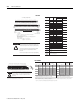
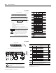
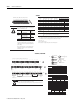
Row 1
Row 2
Row 3
A
B
C
Channel 0 Termi nals
5
Ch ann el 1 Termina ls
5
Type of
Inputs
Pow er Inpu t
RET
6
Pow er Inpu t
RET
6
Frequency
24V dc
IEC 3
Proximity
1
,2
A-7 A-6 A-3 A-8 A-9 A-12
24V dc
Contact
Switch
3
A-7 A-6 A-3 A-8 A-9 A-12
500mV ac
Magnetic
Pickup
A-7 A-5 A-3 A-8 A-10 A-12
50mV ac
Magnetic
Pickup
4
A-7 A-5 A-3 A-8 A-10 A-12
6V ac
Vortex
A-2 A-1 A-3 A-13 A-14 A-12
3V ac
Vortex
A-2 A-0 A-3 A-13 A-15 A-12
1
As defined by standard IEC 1131-2.
2
RET not used on 2-wire devices.
3
Add external resistor from 24V to F or G for wire-off detection (0.4mA).
4
Add a jumper between 50mV and RET (Frequency - channel 0=4 to 3; channel 1=11 to
12). (Gate - channel 0=21 to 20; channel 1=28 to 29).
5
6
All 4 RET terminals (ch 0 and 1, Freq, Gate) are internally connected together.
Ch anne l 0 Termi nals
5
Ch ann el 1 Term ina ls
5
Type of
Inputs
Pow er Inpu t
RET
6
Pow er Inpu t
RET
6
Gate
24V dc
IEC 3
B-24 B-23 B-20 B-25 B-26 B-29
24V dc
Contact
Switch
3
B-24 B-23 B-20 B-25 B-26 B-29
500mV ac
Magnetic
Pickup
B-24 B-22 B-20 B-25 B-27 B-29
50mV ac
Magnetic
Pickup
4
B-24 B-22 B-20 B-25 B-27 B-29
1
As defined by standard IEC 1131-2.
2
RET not used on 2-wire devices.
3
Add external resistor from 24V to F or G for wire-off detection (0.4mA).
4
Add a jumper between 50mV and RET (Frequency - channel 0=4 to 3; channel 1=11 to
12). (Gate - channel 0=21 to 20; channel 1=28 to 29).
5
6
All 4 RET terminals (ch 0 and 1, Freq, Gate) are internally connected together.
Chan nel 0 Termi nal s
1
Chan nel 1 Termi nal s
1
Output Al arm
Co nne ct ion s
Sply
+
Sply
RET
Ou t
+
Ou t
RET
Sply
+
Sply
RET
Ou t
+
Ou t
RET
Supply Connection C-37 C-39 C-46 C-48
Output Connection B-17 B-18 B-31 B-32
1
!
To reduce the susceptibility to noise, power analog modules and digital modules from separate power supplies. Do not exceed a length of 10m (33ft) for dc
power cabling.
Do not daisy chain power or ground from this module to any ac or dc digital module terminal base unit.
Also, total current draw through the terminal base unit is limited to 10A. Separate power connections to the terminal base unit may be necessary.
ATTENTION
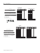
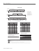
Connections are for 1794-TB3G, -TB3GK and -TB3GS
(TB3G shown)
NC
NC
NC
NC
Chassis
Gnd
Chassis
Proximity
1
,2
Connect cable shields to Chassis Gnd terminals.
Connect cable shields to Chassis Gnd terminals.
Connect cable shields to Chassis Gnd terminals.
All '24V Pwr' and 'RET' terminals
are sourced power provided for
the sensors. Do not connect external
power to these terminals.
These outputs provide power for up
to four 24Vdc devices at 15mA each--for
a total of 60mA. Channel 0 '24V Pwr'
and channel 1 '24V Pwr' are each current
limited to 30mA maximum.
NC = No connect
1794-IJ2, 1794-IJ2K