
User manual

Publication CIG-WD001B-EN-P - May 2005
1794 FLEX I/O Modules 19-11
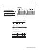
16 0 2 4 6 8 10 1 2 1 4 33
34 1 3 5 7 9 11 13 15 51
16 33
34 51
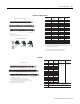
Even Numbered Terminals 0 through 14
Odd Numbered Terminals 1 through 15
16, 0, 2, 4, 6,
8. 10. 12. 14. 33
34, 1, 3, 5, 7,
9, 11, 13, 15, 51
B
C
012 34567
8
9 101112 131415
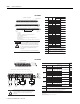
Current
Input
Current
Input
Voltage
Input
A
B
C
Current
Input
34-51
16-33
0-15
I
+-
-
+
+
II I
+
-
-
-
-
+
+
+
+
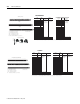
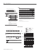
ac or dc
4-Wire Current
Transmitter
dc only
3-Wire Current
Transmitter
Current Only
2-Wire Current
Transmitter and External
Power Supply
dc only
3-Wire
Transmitter
24V dc
Power Supply
IRVRIRVRIRVRIRVR
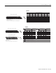
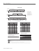
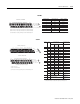
Signal Type Label Ma rkings
0
Current Input I0
Current Return I0 Ret
Voltage Input V0
Voltage Return V0 Ret
1
Current Input I1
Current Return I1 Ret
Voltage Input V1
Voltage Return V1 Ret
2
Current Input I2
Current Return I2 Ret
Voltage Input V2
Voltage Return V2 Ret
3
Current Input I3
Current Return I3 Ret
Voltage Input V3
Voltage Return V3 Ret
Common
TB2, TB3, TB3K, TB3S: Terminals 16 through 33 are internally connected in the terminal base unit
TB3T, TB3TS: Terminals 16, 17, 19, 21, 23, 25, 27, 29, 31, and 33 are internally connected in the terminal base unit
TBN, TBNK: Terminals 16 and 33 are internally connected in the terminal base unit
TB2,TBN, TBNK: Terminals 34 and 51 are internally connected in the terminal base unit
TB3, TB3K, TB3S: Terminals 34 through 51 are internally connected in the terminal base unit
TB3T, TB3TS: Terminals 34, 35, 50, and 51 are internally connected in the terminal base unit
Chassis Gnd TB3T, TB3TS: Terminals 39 through 46 are internally connected to chassis gnd
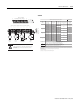
1794-T BN, 1794-TBNK
!
ATTENTION
1794-TB2, 1794-TB3, 1794-TB3K, 1794-TB3S, 1794-TB3T, 1794-TB3TS
Shiel d (TB 3T/TB 3TS)
A-0
C-39
B-0
A-1 C-1
A-2
C-40
B-2
A-3 C-3
A-4
C-41
B-4
A-5 C-5
A-6
C-42
B-6
A-7 C-7
A-8
C-43
B-8
A-9 C-9
A-10
C-44
B-10
A-11 C-11
A-12
C-45
B-12
A-13 C-13
A-14
C-46
B-14
A-15 C-15
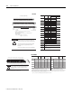
Connect any signal wiring shields to functional ground as near as possible to the module when using the 1794-TB2, -TB3, -TB3K, -TB3S, -TBN and -TBNK.
With the 1794-TB3T and -TB3TS, use terminals C-39 through C-46 for signal wiring shields.
Connect +V to C-34.
Connect +V common to B-16.
Use B-33 and C-51 for daisy chaining to the next terminal base unit.
+V dc
Input
Terminal
Input
Terminal
Input
Channel
34 & 51
for TB2
Only connect either a voltage input or a current input per channel, not both.
To reduce susceptibility to noise, power analog and digital modules from
separate power supplies. Do not exceed a length of 3M (9.8 ft) for DC
power cabling.
1794-TBN, -TBNK1794-TB2, -TB3, -TB3K, -TB3S, -TB3T, -TB3TS
1794-IF4I