
User manual

Publication CIG-WD001B-EN-P - May 2005
19-4 1794 FLEX I/O Modules
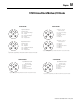
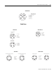
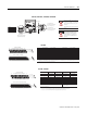
Input Channel
Input Terminal s 120V ac Co mmon
L2
Inp ut Termina ls 120V ac Commo n
L2
0 A-0 A-1 B-0 C-1
1 A-2 A-3 B-2 C-3
2 A-4 A-5 B-4 C-5
3 A-6 A-7 B-6 C-7
4 A-8 A-9 B-8 C-9
5 A-10 A-11 B-10 C-11
6 A-12 A-13 B-12 C-13
7 A-14 A-15 B-14 C-15
A = even numbered input terminals 0 thru 14 for customer input connections;
corresponding odd numbered 120V ac common L2 terminals 1 through 15 for
customer connections from isolated power supply
B = even numbered input terminals 0 through 14 for
customer input connections
C = odd numbered terminals 1 through 15 for 120V ac L2
common connections from isolated power supply
16 0 2 4 6 8 1 0 1 2 1 4 3 3
34 1 3 5 7 9 11 13 15 51
0 1 2 3 4 5 6 7 8 9 10 11 12 13 14 15
1716 18 19 20 21 22 23 24 25 26 27 28 29 30 31 32
33
34 35 36 37 38 39 40 41 42 43 44 45 46 47 48 49
51
50
16 33
34 51
16, 0, 2, 4, 6,
8. 10. 12. 14. 33
34, 1, 3, 5, 7,
9, 11, 13, 15, 51
B
C
B
C
A
0-15
16-33
34-51
Terminals 35 through 50 are not used on 1794-TB2
Even numbered terminals 0 through 14
Odd numbered terminals 1 through 15
Auxiliary terminal strips are required to connect 120V ac L1 of each isolated power supply to the input device that it is driving.
1794-TBN, 1794-TBNK
1794-TB2, 1794-TB3, 1794-TB3K, 1794-TBB3S
1794-TBN, 1794-TBNK1794-TB2, 1794-TB3, 1794-TB3K, 1794-TBB3S
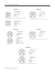
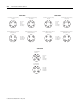
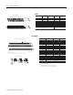
1794-IA8I
Input
1
Common Sup ply
Sink Input Channel
0 A-0 B-17 C-35
1 A-1 B-18 C-36
2 A-2 B-19 C-37
3 A-3 B-20 C-38
4 A-4 B-21 C-39
5 A-5 B-22 C-40
6 A-6 B-23 C-41
7 A-7 B-24 C-42
8 A-8 B-25 C-43
9 A-9 B-26 C-44
Source Output Channel
0 A-10 B-27 C-45
1 A-11 B-28 C-46
2 A-12 B-29 C-47
3 A-13 B-30 C-48
4 A-14 B-31 C-49
5 A-15 B-32 C-50
+V dc C-34 through C-51
Common B-16 through B-33
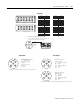
17 1 8 1 9 2 0 2 1 2 2 2 3 2 4 2 5 2 6 2 7 2 8 2 9 3 0 3 1 3 2 33
0 1 2 3 4 5 6 7 8 9 1 0 1 1 1 2 1 3 1 4 1 5
16
35 3 6 3 7 3 8 3 9 4 0 4 1 4 2 4 3 4 4 4 5 4 6 4 7 4 8 4 9 5 0 5 1
34
Inputs
Commons
(1794-TB3 shown)
Connect +V to C-34
Connect +V common to B-16
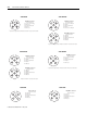
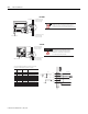
-V
Voltage
In +V
Voltage
Out +V
Voltage
A
B
C
Use B-33 and C-51 for daisy chaining to next terminal base unit
Common
-V
Common
Outputs
A
B
C
0-15
16-33
35-51
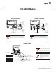
= Sink Input
= Common
= +V dc
2-Wire Device
(Sourcing Output)
3-Wire Device
(Sourcing Output)
A
B
C
2 and 3-Wire Input Wiring
1. Two-wire input devices use input and supply terminals. Three-wire devices use input,
common and supply terminals.
+V common internally connected to terminal 16 through 33.
+V dc power internally connected to terminal 34 through 51.
1794-TB3, 1794-TB3K, 1794-TB3S
1794-IB10XOB6