
User manual

Publication CIG-WD001B-EN-P - May 2005
1794 FLEX I/O Modules 19-3
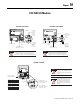
COM
24V
Remote I/O Cable Connector
(connections listed on left)
Connect: To:
BLU Wire
1
Shield Wire SH
CLR Wire 2
1SH2
24V Common
Use terminal to pass
24V common to next module
in series (if necessary)
24V dc
Use terminal to pass
24V dc power to next module
in series (if necessary)
If this is the last adapter, you must terminate the
remote I/O link here. Use a terminating resistor
connected across terminals 1 and 2. Refer to your
processor manual for information on the size of
the resistor.
Power wiring must be less than 10 meters (33ft)
in length.
ATTENTION
If you connect or disconnect the network cable
with power applied to the adapter or any device
on the network, an electrical arc can occur.
This could cause an explosion in hazardous
location installations. Be sure that power is
removed or the area is nonhazardous before
proceeding.
WARNING
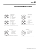
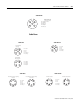
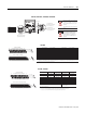
1794-ASB, 1794-ASB2, 1794-ASBK, 1794-ASB2K
Inp ut Terminals 120V ac Supply Input Termin als 120V ac Supply
Chan nel
TB3, TB3K, TB3S TBN, TBNK Channe l
0 A-0 B-0 C-35 8 A-8 B-8 C-43
1 A-1 C-1 C-36 9 A-9 C-9 C-44
2 A-2 B-2 C-37 10 A-10 B-10 C-45
3 A-3 C-3 C-38 11 A-11 C-11 C-46
4 A-4 B-4 C-39 12 A-12 B-12 C-47
5 A-5 C-5 C-40 13 A-13 C-13 C-48
6 A-6 B-6 C-41 14 A-14 B-14 C-49
7 A-7 C-7 C-42 15 A-15 C-15 C-50
B =
C =
16 0 2 4 6 8 10 12 1 4 3 3
34 1 3 5 7 9 11 13 15 51
0 1 2 3 4 5 6 7 8 9 10 11 12 13 14 15
1716 18 19 20 21 22 23 24 25 26 27 28 29 30 31 32
33
34 35 36 37 38 39 40 41 42 43 44 45 46 47 48 49
51
50
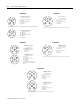
1794-TBN, 1794-TBNK
16 33
34 51
16, 0, 2, 4, 6,
8. 10. 12. 14. 33
34, 1, 3, 5, 7,
9, 11, 13, 15, 51
B
C
B
C
A
0-15
16-33
34-51
11
1 - Auxiliary terminal strips are required when using the 1794-TBN or TBNK.
A = Input terminals on the 1794-TB3, TB3K and TB3S. B0 - B14 and C1 -C15 are input terminals on the 1794-TBN and TBNK.
Even numbered terminals 0 through 14
Odd numbered terminals 1 through 15
B-16 through B-33 are internally connected on the 1794-TB3, TB3K and -TB3S. B-16 and B-33 are internally connected on the 1794-TBN and TBNK. Connect 120V ac L2 to B-16.
C-34 through C-51 are internally connected on the 1794-TB3, TB3K and -TB3S. C-34 and C-51 are internally connected on the 1794-TBN and TBNK. Connect 120V ac L1 to C-34.
1794-TB3, 1794-TB3K, 1794-TBB3S
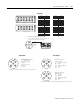
TB3, TB3K, TB3S TB3, TB3K, TB3S TBN, TBNK TB3, TB3K, TB3S
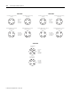
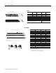
1794-IA16
Input Channel
Inpu t Terminal s 120V ac Su pp ly Inpu t Terminal s 120V ac Su pp ly
0A-0
A-1
1
/C-35
B-0
C-1
2
1A-2
A-3
1
/C-37
B-2
C-3
2
2A-4
A-5
1
/C-39
B-4
C-5
2
3A-6
A-7
1
/C-41
B-6
C-7
2
4A-8
A-9
1
/C-43
B-8
C-9
2
5A-10
A-11
1
/C-45
B-10
C-11
2
6A-12
A-13
1
/C-47
B-12
C-13
2
7A-14
A-15
1
/C-49
B-14
C-15
2
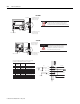
A = input terminals
B = common terminals
C = power terminals (C-34 through C-51 for TB3, TB3K and TB3S; C-34 and C-51 for TB2)
B = even numbered terminals B-0 through B-14, ac common
terminals B-16 and B-33
C = Power Terminals C-34 and C-51, and odd numbered
terminals 1 through 15
1 A-1, 3, 5, 7, 9, 11, 13 and 15 on 1794-TB3, -TB3K, -TB3S, and -TB2 are internally connected in the module to 120V ac L1.
2 C-1, 3, 5, 7, 9, 11, 13 and 15 on 1794-TBN and TBNK are internally connected in the module to 120V ac L1.
16 0 2 4 6 8 10 1 2 1 4 33
34 1 3 5 7 9 11 13 15 51
0 1 2 3 4 5 6 7 8 9 10 11 12 13 14 15
1716 18 19 20 21 22 23 24 25 26 27 28 29 30 31 32
33
34 35 36 37 38 39 40 41 42 43 44 45 46 47 48 49
51
50
16 33
34 51
16, 0, 2, 4, 6,
8. 10. 12. 14. 33
34, 1, 3, 5, 7,
9, 11, 13, 15, 51
B
C
B
C
A
0-15
16-33
34-51
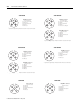
Terminals 35 through 50 are not used on 1794-TB2
Even numbered terminals 0 through 14
Odd numbered terminals 1 through 15
Connect 120V ac L2 (common) to B-16
Connect 120V ac L1 to C-34
1794-TBN, 1794-TBNK
1794-TB2, 1794-TB3, 1794-TB3K, 1794-TB3S
1794-TBN, 1794-TBNK1794-TB2, 1794-TB3, 1794-TB3K, 1794-TBB3S
1794-IA8, 1794-IA8K