
User manual

Publication CIG-WD001B-EN-P - May 2005
18-4 1792D ArmorBlock MaXum I/O Blocks
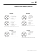
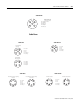
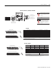
Input Micro-Connector
(View into Socket)
Pin 1 Sensor Source voltage
Pin 3 Return Logic Ground
1
Pin 4 Input A
Pin 5 Not Used
1
Logic Ground is approximately 0.4V above DeviceNet V- measured at the module.
Pin 2 Not Used
1792D-8BV0D
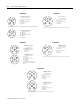
Input Micro-Connector
(View into Socket)
Pin 1 Sensor Source voltage A
Pin 2 Input B
Pin 3 Return Logic Ground
1
Pin 4 Input A
Pin 5 Sensor Source voltage B
Output Micro-Connector
(View into Socket)
Pin 1 Not Used
Pin 2 Output B
Pin 3 Auxiliary Power Ground
Pin 4 Output A
Pin 5 Not Used
1
Logic Ground is approximately 0.4V above DeviceNet V- measured at the module.
1792D-8BVT8CD
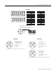
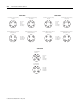
Input Micro-Connector
(View into Socket)
Pin 1 Sensor Source voltage
Pin 2 Input B
Pin 3 Return Logic Ground
1
Pin 4 Input A
Pin 5 Not Used
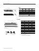
Output Micro-Connector
(View into Socket)
Pin 1 Not Used
Pin 2 Output B
Pin 3 Auxiliary Power Ground
Pin 4 Output A
Pin 5 Not Used
1
Logic Ground is approximately 0.4V above DeviceNet V- measured at the module.
1792D-8BVT8D
1
5
3
4
2
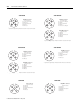
Input Micro-Connector
(View into Sockets)
Pin 1 Sensor Source Voltage
Pin 2 Input B
Pin 3 Return Logic Ground
1
Pin 4 Input A
Pin 5 Not Used
1.
Logic Ground is approximately 0.4V above DeviceNet V-measured at the module.
1792D-8BVTOD
1
5
3
4
2
Micro-Connector
(View into Sockets)
Pin 1 Not Used
Pin 2 Not Used
Pin 3 Auxiliary Power Ground
Pin 4 Output
Pin 5 Not Used
1792D-OB4D
Output Micro-Connector
(View into Sockets)
Pin 1 Not Used
Pin 2 Not Used
Pin 3 Auxiliary Power Ground
Pin 4 Output A
Pin 5 Not Used
1792D-OB8D