
User manual

Publication CIG-WD001B-EN-P - May 2005
1792D ArmorBlock MaXum I/O Blocks 18-3
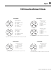
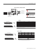
11 12 13 14 15 16 17 18 19 20
21 22 23 24 25 26 27 28 29 30
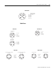
Module Connector
1 2 3 4 5 6 7 8 9 10
10 9 8 7 6 5 4 3 2 1
20 19 18 17 16 15 14 13 12 11
30 29 28 27 26 25 24 23 22 21
Mating/Harness Connector
1PWR1+
2 I N_0 (GR P 1 )
3 I N_1 (GR P 1 )
4 I N_2 (GR P 1 )
5 I N_3 (GR P 1 )
6 I N_0 (GR P 2 )
7 I N_1 (GR P 2 )
8 I N_2 (GR P 2 )
9 I N_3 (GR P 2 )
10 PWR 2+
11 PWR 1+
12 PWR 1-
13 PWR 1-
14 PWR 1-
15 PWR 1-
Pin Number Signal
16 PWR 2-
17 PWR 2-
18 PWR 2-
19 PWR 2-
20 PWR 2+
21 PWR 1+
22 OU T_0 (G RP 1 )
23 OU T_1 (G RP 1 )
24 OU T_2 (G RP 1 )
25 OU T_3 (G RP 1 )
26 OU T_0 (G RP 2 )
27 OU T_1 (G RP 2 )
28 OU T_2 (G RP 2 )
29 OU T_3 (G RP 2 )
30 PWR 2+
Pin Number Signal
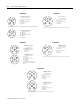
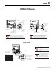
Pin 1 Drain
(not connected internally)
Pin 2 V+
Pin 3 V-
Pin 4 CAN_H
Pin 5 CAN_L
1
2
3
4
5
42286
Looking into connector pins
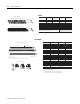
Connect the DeviceNet Cable to the Module
Connect the DeviceNet wiring to the 5-pin micro-connector on the
module. The micro-connector pinout is shown below.
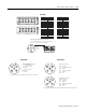
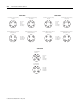
1792D-88HC
Input/ Output Micro-Connector
(View into Socket)
Pin 1 Sensor Source Voltage
Pin 2 Output B
Pin 3 Return Logic Ground
1
Pin 4 Input A
Pin 5 Not Used
1Logic Ground is approximately 0.4V above DeviceNet V-measured at the module.
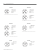
(view into socket)
Pin 1 Sensor Source voltage
Pin 2 Input B
Pin 3 Return Logic Ground
1
Pin 4 Input A
Pin 5 PE
(view into socket)
Pin 1 Not Used
Pin 2 Output B
Pin 3 Auxiliary Power Ground
Pin 4 Output A
Pin 5 PE
1
Logic Ground is approximately 0.4V above DeviceNet V- measured at the module.
Input Micro-Connector
Output Micro-Connector
1792D-8BIO8E 1792D-8BT8PE