
User manual

Publication CIG-WD001B-EN-P - May 2005
2-8 1734 POINT I/O Modules
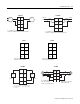
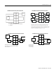
NC NC
Chas
Gnd
C
VV
C
V dc
01
32
45
76
Chas
Gnd
NC = No Connection Chas Gnd = Chassis Ground
C = Common V = 12/24V dc
This supply will
be connected to
the internal
power bus.
NC NC
Chas
Gnd
L2/N
L1 L1
V ac
01
32
45
76
This supply will be
connected to the
internal power bus.
Chas
Gnd
NC = No Connection Chas Gnd = Chassis Ground
L2/N
L1 = 120/240V ac L2/N = ac Neutral
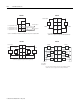
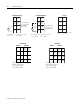
0
1
6
7
D+
V+
Shield
C+
D-
V-
I1
C-
D = Data I1 = Digital Sourcing Input 1
C = Clock V = SSI Sensor
3
5
2
4
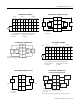
1734-PDN 120/240V ac 1734-SSI1734-PDN (12/24V dc)
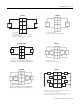
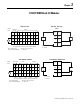
AAret
B
Z
Out
0
Out
1
Zret
Bret
A, B, Z, Aret, Bret, and Zret = inputs
Chas Gnd = Chassis Ground
-Vaux = Auxiliary Supply
+Vaux = Auxiliary Supply
01
32
45
76
Chas
Gnd
RET
0
-Vaux -Vaux
01
32
45
76
RET
1
+Vaux +Vaux
Chas
Gnd
Module 1 Module 2
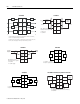
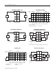
AAret
B
Z
Out
0
Out
1
Zret
Bret
A, B, Z, Aret, Bret, and Zret = inputs
Chas Gnd = Chassis Ground
-Vaux = Auxiliary Supply
+Vaux = Auxiliary Supply
01
32
45
76
Chas
Gnd
RET
0
-Vaux -Vaux
01
32
45
76
RET
1
+Vaux +Vaux
Chas
Gnd
Module 1 Module 2
1734-VHSC24 1734-VHSC5