
User manual

Publication CIG-WD001B-EN-P - May 2005
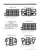
2-6 1734 POINT I/O Modules
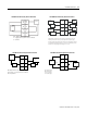
Out
0
Out
1
Chas
Gnd
Chas
Gnd
CC
VV
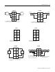
Out = Output channel
Chas Gnd = Chassis ground
V = Not used
2
4
6
Current
Output
Device
2-wire
4-wire
ac or
dc
Current
Output
Device
C = Common
1
7
5
3
0
Out 0 Out 1
Out 3Out 2
Load
Load
Load
0
2
6
3
1
7
45
Load
Load
Load
Load
Load
CC
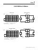
Common must be daisy chained from a 1734 adapter, 1734-FPD, 1734-EP24DC,
or from a user-supplied auxiliary terminal block.
The 24V dc power to the module is supplied by the internal power bus and comes
from the same 1734 adapter, 1734-FPD, or 1734-EP24DC as common.
Out 3Out 2
Out 3Out 2
1734-OE2C1734-OB8E
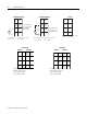
Out
0
Out
1
Chas
Gnd
Chas
Gnd
CC
VV
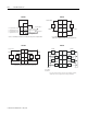
Out = Output channel
Chas Gnd = Chassis ground
C = Common
V = 12/24V Supply
3
5
7
01
2
4
6
Voltage
Output
Voltage
Output
1734-OE2V
Out 0
Out 1
NC
NC
C
C
V
V
Load
Load
V = 12/24V dc, C = Common
Field power is supplied from internal power bus
0
2
6
4
3
5
7
1
1734-OV2E
Out 0 Out 1
Out 3Out 2
V
V
V
V
Load
Load
Load
Load
V = 12/24V dc, C = Common
Field power is supplied from internal power bus
0
2
6
3
1
7
45
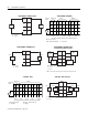
CC
VV
Load
0
2
4
6
3
5
7
1
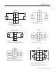
Power
Supply
Load
Power
Supply
Out
0A
Out = Output channel relay contacts
V = Supply (can range from +5V dc to 240V ac)
C = Common
Out
1A
Out
0B
Out
1B
1734-OV4E 1734-OW2 Load Powered by External Power Bus