
User manual


Publication CIG-WD001B-EN-P - May 2005
1771 I/O Modules 12-13
SH R4 I4 R3 I3 R2 I2 R1 I1
W1 S4 O4 S3 O3 S2 O2 S1 O1
+
±
+
±
+
±
10V Excitation
Sense
0±30mV W
eight Signal
Junction Box
±
+
C2 Cal
!
+
+
+
+
±
±
±
±
To Load Cell
RTP
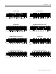
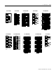
I1 ± Excitation to junction box
R1 ± Sense from junction box
S1 Shield
O1 ± C2-Cal from junction box
1
I2 ± Signal from junction box
R2 + Signal from junction box
S2 Shield
O2 + C2-Cal from junction box
1
I3 + Sense from junction box
1
These
connections apply only to those applications using C2 Second-Generation-Calibration load points.
A sense loop is required when using C2 Second-Generation-Calibration.
R3 + Excitation to junction box
S3 Shield
O3 Not Used
I4 Not Used
R4 Not Used
S4 Shield
O4 Not Used
SH Ground
W1 Not Used
ATTENTION: The C2-Cal connections
apply only to those applications using
C2 Second-Generation-Calibration
load points
SH R4 I4 R3 I3 R2 I2 R1 I1
W1 S4 O4 S3 O3 S2 O2 S1 O1
+
±
+
±
±
10V Excitation
0±30mV W
eight Signal
+
C2 Cal
!
Junction Box
+
+
+
±
±
±
To Load Cell
RTP
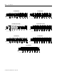
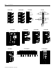
I1
± Excitation to junction box
R1 I1 on RTP
S1 Shield
O1 ± C2-Cal from junction box
1
I2 ± Signal from junction box
R2 + Signal from junction box
S2 Shield
O2 + C2-Cal from junction box
1
I3 R3 on R TP
1
These
connections apply only to those applications using C2 Second-Generation-Calibration load points. A sense loop is
required when using C2 Second-Generation-Calibration.
R3 + Excitation to junction box
S3 Shield
O3 Not Used
I4 Not Used
R4 Not Used
S4 Shield
O4 Not Used
SH Ground
W1 Not Used
ATTENTION: The C2-Cal connections
apply only to those applications using
C2 Second-Generation-Calibration
load points
SH R4 I4 R3 I3 R2 I2 R1 I1
W1 S4 O4 S3 O3 S2 O2 S1 O1
+
±
+
±
±
0±30mV W
eight Signal
+
C2 Cal
Sense
10V
External
Power Supply
!
!
Junction Box
+
+
+
±
±
±
To Load Cell
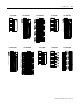
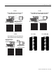
1 on RTP
± Sense from junction box
Shield
± C2-Cal from junction box
1
± Signal from junction box
+ Signal from junction box
Shield
+ C2-Cal from junction box
1
+ Sense from junction box
I1
R1
S1
O1
I2
R2
S2
O2
I3
1
These
connections apply only to those applications using C2 Second-Generation-Calibration load points. A sense loop is
required when using C2 Second-Generation-Calibration.
R3 Not Used
S3 Shield
O3 Not Used
I4 Not Used
R4 Not Used
S4 Shield
O4 Not Used
SH Ground
W1 Not Used
ATTENTION: The C2-Cal connections
apply only to those applications using
C2 Second-Generation-Calibration
load points
ATTENTION: In this configuration, you
must also jumper +excitation to +sense
and +/-excitation to +/-sense in the
junction box.
1771-WS
Connecting Wires from the Junction Box to the
Remote Termination Panel - Using the
1771-WS
Connecting Wires from the Junction Box to the Remote
Termination Panel - With the Module-Generated
1771-WS
Connecting Wires from the Junction Box to the
Remote Termination Panel - With the Voltage
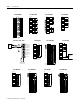
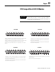
In 00
In 01
In 02
In 03
n.c.
In 04
In 05
In 06
In 07
n.c.
In 10
In 11
In 12
In 13
n.c.
In 14
In 15
In 16
In 17
n.c.
In 00-
In 01-
In 02-
In 03-
n.c.
In 04-
In 05-
In 06-
In 07-
n.c.
In 10-
In 11-
In 12-
In 13-
n.c.
In 14-
In 15-
In 16-
In 17-
n.c.
120/240V ac/dc
Out 00
Out 01
Out 02
Out 03
n.c.
Out 04
Out 05
Out 06
Out 07
n.c.
Out 10
Out 11
Out 12
Out 13
n.c.
Out 14
Out 15
Out 16
Out 17
n.c.
L1 - 00
L1 - 01
L1 - 02
L1 - 03
n.c.
L1 - 04
L1 - 05
L1 - 06
L1 - 07
n.c.
L1 - 10
L1 - 11
L1 - 12
L1 - 13
n.c.
L1 - 14
L1 - 15
L1 - 16
L1 - 17
n.c.
120/240V ac
1771-sc IM16 1771-sc OMI16 (WN)