
User manual

1 Publication CIG-WD001B-EN-P - May 2005
Chapter
12
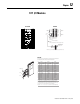
1771 I/O Modules
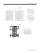
Chs Gnd
5V Com
G0
G1
F0 TTL
F0 Ret
F1 TTL
F1 Ret
+24V 1
+24V 2
F2 TTL
F2 Ret
F3 TTL
F3 Ret
G2
G3
Cu V dc 1
Out 1
Cu V dc 2
Out 3
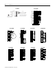
n.c.
n.c.
G0 Ret
G1 Ret
F0 500mV
F0 In
F1 500mV
F1 In
dc 1 Ret
dc 2 Ret
F2 500mV
F2 In
F3 500mV
F3 In
G2 Ret
G3 Ret
Out 0
Out 2
Cu V 1 Ret
Cu V 2 Ret
50
mV
+
500
mV
+
TTL
+
Prox
++
++
+
+
+
+
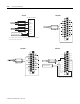
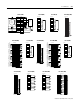
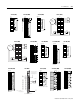
Blue
Shield
Clear
Terminator Resistor
(Cat. No. 1770-XT)
150 ohm 0.5 W
Terminator Resistor
(Cat. No. 1770-XS or 1770-XT)
150 ohm 0.5 W
Line 1
Shield
Line 2
Line 1
Shield
Line 2
Channel
No. 4
Channel
No. 2
Line 1
Shield
Line 2
Channel
No. 3
Blue
Channel
No. 1
Shield
Clear
Line 2
1770-CD Twinaxial cable
Terminals of field wiring arm of 1770-AS adapter module
NOTE: Absence of a terminator resistor can cause block transfer errors
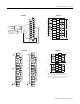
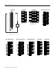
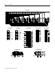
1771-CFM 1771-DA
DH-485 port
Port 2
Port 1
Pin RS-232 RS-422 RS-485
1
chassis/shield chassis/shield chassis/shield
2 TXD
N/A N/A
3 RXD
N/A N/A
4 RT S
N/A N/A
5 CTS
N/A N/A
6 DSR
N/A N/A
7 common common common
8 DCD
N/A N/A
9 common common common
10 common common common
14
N/A
TXD TXD/RXD
16
N/A
RXD
N/A
18
N/A
RXD'
N/A
20 DTR
N/A N/A
25
N/A
TXD' TXD'/RXD'
These pins are not a No Connection (N/C). In RS-232 mode, the RS-422 and RS-485
load is still present and should not be connected to any device in this mode.
In RS-422 and RS-485 modes, these pins are still connected to their
RS-232
drivers
and receivers. Do not use these pins in either RS-422 or RS-485 mode.
Important: Pins 1 1, 12, 13, 15, 17, 19, 21, 22, 23 and 24 are a No Connection (N/C)
1
1
1
1-
1
2-
2
2
2
2
2
2
2
2
2
2
2
2
2
2
2
2
Ports 1 and 2 can be configured for RS-232, RS-422 and RS-485 communications.
pin configurations for these modes are listed in the table below.
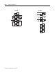
1771-DB