
User manual


1 Publication CIG-WD001B-EN-P - May 2005
Chapter
11
1769 Compact I/O Modules
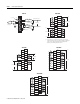
A
A
B
B
Z
Z
A1(+)
A1(–)
B1(+)
B1(–)
Z1(+)
Z1(–)
GND
VS
+VDC
COM
Cable
(1)
Power
Supply
Allen-Bradley 845H
Series differential
encoder
shield/housing
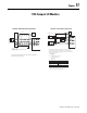
Connect only if housing is electronically isolated from
the motor and ground.
Shield
Module Inputs
Earth
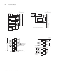
1. Refer to your encoder manual for proper cable type. The type of cable used should be twisted pair, individually
shielded cable with a maximum length of 300m (1000 ft.).
VS
A1(+)
A1(–)
B1(+)
B1(–)
Z1(+)
Z1(–)
+VDC
COM
VS
OUT
COM
OUT
COM
VS
OUT
COM
R
1
Power
Supply
Module Inputs
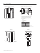
Solid-State
Switch
Proximity Sensor
Photo-electric Sensor
with Open Collector
Sinking Output
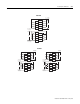
1.
where:
R = maximum pull-up resistor value
Vdc = power supply voltage
Vmin = 2.6V dc
Imin = 6.8 mA
(a)
(a)
5V dc 35 2 Ω
12 V dc 1 38 2 Ω
24 V dc 3 14 7 Ω
R
V
dc
Vmin
–()
Imin
----------------------------------------=
Maximum Pull-Up Resistor ValuePower Supply Voltage (V dc)
Resistance values may change, depending on your application. The
minimum resistor (R) value depends on the current sinking capability
of the sensor. Refer to your sensor's documentation.
External resistors are required if they are not internal to the sensor. The pull-up
resistor (R) value depends on the power supply value. The table below shows the
maximum resistor values for typical supply voltages. To calculate the maximum resistor
value, use the following formula:
1769-HSC – Differential Encoder applications 1769-HSC – Discrete Device applications