
User manual

Publication CIG-WD001B-EN-P - May 2005
1762 I/O on MicroLogix 1200 Controllers 9-13
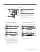
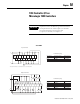
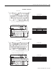
OUT 2
OUT 0
OUT 3
OUT 1
VAC-VDC
0
CR
CR
CR
OUT 6
OUT 4
OUT 7
OUT 5
CR
CR
CR
OUT 10
OUT 8
OUT 11
OUT 9
VAC-VDC
1
CR
CR
CR
OUT 14
OUT 12
OUT 15
OUT 13
CR
CR
CR
L1 or +DC
L2 or -DC
L1 or +DC
L2 or -DC
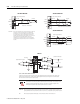
Be careful when stripping wires. Wire fragments that fall into a
module could cause damage when power is applied.
Once wiring is complete, ensure the module is free of all
metal fragments.
Surge Suppression – Connecting surge suppressors across your external inductive
load will extend the life of the relay contacts. For additional details, refer to
Industrial Automation Wiring and Grounding Guidelines, Allen-Bradley publication 1770-4.1.
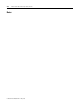
1762-OW16
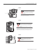
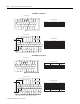
OUT 5
VAC-VDC
1
OUT 2
OUT 0
OUT 7
OUT 4
OUT 3
OUT 1
VAC-VDC
0
OUT 6
CR
CR
CR
CR
CR
CR
L1 or +D C
L2 or -DC
L1 or +D C
L2 or - DC
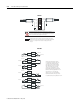
Be careful when stripping wires. Wire fragments that fall into a
module could cause damage when power is applied.
Once wiring is complete, ensure the module is free of all
metal fragments.
Surge Suppression – Connecting surge suppressors across your external inductive
load will extend the life of the relay contacts. For additional details, refer to
Industrial Automation Wiring and Grounding Guidelines, Allen-Bradley publication 1770-4.1.
1762-OW8