
User manual


Publication CIG-WD001B-EN-P - May 2005
9-12 1762 I/O on MicroLogix 1200 Controllers
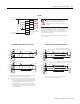
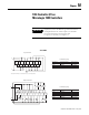
V out 3
V out 2
V out 1
V out 0
I out 3
I out 2
I out 1
I out 0
COM
COM
Current Load
Voltage Load
Analog outputs may fluctuate for less than a second when power is applied or
removed. This characteristic is common to most analog outputs. While the majority of
loads will not recognize this short signal, it is recommended that preventive measures
be taken to ensure that connected equipment is not affected.
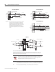
TIP
Grounding the cable shield at the module end only usually provides sufficient noise
immunity. However, for best cable shield performance, earth ground the shield at both
ends, using a 0.01 µF capacitor at one end to block AC power ground currents,
if necessary.
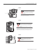
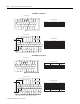
1762-OF4
L1-0
L1-1
L1-2
L1-3
L1-4
L1-5
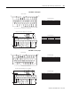
OUT0 N.C.
OUT0 N.O.
OUT1 N.C.
OUT1 N.O.
OUT2 N.C.
OUT2 N.O.
OUT3 N.O.
OUT3 N.C.
OUT4 N.C.
OUT4 N.O.
OUT5 N.C.
OUT5 N.O.
CR
CR
CR
CR
CR
CR
L1 OR +DC
L1 OR +DC
L1 OR +DC
L1 OR +DC
L1 OR +DC
L1 OR +DC
L2 OR -DC
L2 OR -DC
L2 OR -DC
L2 OR -DC
L2 OR -DC
L2 OR -DC
This product is intended to be mounted
to a well-grounded mounting surface such
as a metal panel. Additional grounding
connections from the module’s mounting
tabs or DIN rail (if used) are not required
unless the mounting surface cannot be
grounded. For more information, refer to
Industrial Automation Wiring and Grounding
Guidelines, Allen-Bradley publication 1770-4.1.
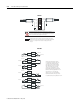
Surge Suppression – Connecting surge
suppressors across your external inductive
load will extend the life of the relay contacts.
For additional details, refer to publication 1770-4.1.
1762-OX6I