
User manual

Publication CIG-WD001B-EN-P - May 2005
1762 I/O on MicroLogix 1200 Controllers 9-11
OUT 5
VAC
1
OUT 2
OUT 0
OUT 7
OUT 4
OUT 3
OUT 1
VAC
0
OUT 6
CR
CR
CR
CR
CR
CR
L1
L2
L1
L2
100 to 240V ac
100 to 240V ac
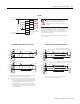
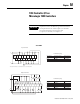
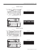
Be careful when stripping wires. Wire fragments that fall into a
module could cause damage when power is applied. Once wiring is
complete, ensure the module is free of all metal fragments.
Miswiring of the module to an AC power source will damage
the module.
To limit the effects of leakage current through triac outputs, a loading resistor can be connected
in parallel with your load. For typical 120V ac applications, use a 15k ohm, 2W resistor. For
typical 240V ac applications, use a 15k ohm, 5W resistor.
1762-OA8
OUT 6
OUT 2
OUT 0
OUT 10
OUT 5
OUT 7
OUT 9
OUT 11
OUT 13
OUT 15
OUT 14
OUT 3
OUT 1
VDC+
OUT 8
OUT 12
CR
CR
CR
CR
CR
CR
CR
CR
CR
CR
OUT 4
DC COM
24V dc (source)
+DC
-DC
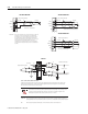
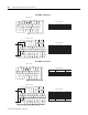
Surge Suppression – Connecting surge suppressors across your external inductive load
will extend the life of the relay contacts. For additional details, refer to Industrial
Automation Wiring and Grounding Guidelines, Allen-Bradley publication 1770-4.1.
Be careful when stripping wires. Wire fragments that fall into a
module could cause damage when power is applied. Once wiring
is complete, ensure the module is free of all metal fragments.
Miswiring of the module to an AC power source will damage
the module.
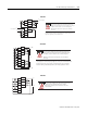
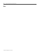
1762-OB16
+DC
24V dc (source)
-DC
OUT 6
OUT 4
OUT 2
OUT 0
OUT 7
OUT 5
OUT 3
OUT 1
+VDC
CR
CR
CR
CR
CR
CR
DC COM
Be careful when stripping wires. Wire fragments that fall into a
module could cause damage when power is applied.
Once wiring is complete, ensure the module is free of all
metal fragments.
1762-OB8