Allen-Bradley I/O Modules 1732, 1734, 1734D, 1738, 1746, 1747, 1756, 1761, 1762, 1764, 1769, 1771, 1790, 1791, 1791D, 1791P, 1791R, 1792D, 1794, 1797, 1798, 1799 Wiring Diagrams
Important User Information Solid state equipment has operational characteristics differing from those of electromechanical equipment. Safety Guidelines for the Application, Installation and Maintenance of Solid State Controls (Publication SGI-1.1 available from your local Rockwell Automation sales office or online at http://www.literature.rockwellautomation.com) describes some important differences between solid state equipment and hard-wired electromechanical devices.
Preface Introduction The purpose for showing these connection diagrams here is to illustrate the following attributes of each I/O module, I/O block, or fixed I/O controller: • the number of inputs and/or outputs • whether there is a single common for all I/O, a common for a set of I/O separate from other sets of I/O, or a signal return for each I/O circuit so that each I/O circuit is isolated from all others • whether an output is a current source or a current sink • whether an input is a source load or a
Preface 2 Abbreviations Symbols In these diagrams we used the following abbreviations: no normally open (contact outputs) nc normally closed (contact outputs) n.c.
Table of Contents Chapter 1 1732 ArmorBlock I/O . . . . . . . . . . . . . . . . . . . . . . . . . . . . . . . . . 1-1 Chapter 2 1734 POINT I/O Modules. . . . . . . . . . . . . . . . . . . . . . . . . . . . . . 2-1 Chapter 3 1734D POINTBlock I/O Modules . . . . . . . . . . . . . . . . . . . . . . . 3-1 Chapter 4 1738 ArmorPoint . . . . . . . . . . . . . . . . . . . . . . . . . . . . . . . . . . . . . . 4-1 Chapter 5 1746 I/O Modules. . . . . . . . . . . . . . . . . . . . . . . . . . . . . . . . . . . . .
Table of Contents 2 Chapter 15 1791D CompactBlock I/O Blocks . . . . . . . . . . . . . . . . . . . . . . . 15-1 Chapter 16 1791P CompactBlock I/O Blocks . . . . . . . . . . . . . . . . . . . . . . . . . . 16-1 Chapter 17 1791R CompactBlock I/O Blocks . . . . . . . . . . . . . . . . . . . . . . . 17-1 Chapter 18 1792D ArmorBlock MaXum I/O Blocks . . . . . . . . . . . . . . . . . 18-1 Chapter 19 1794 FLEX I/O Modules . . . . . . . . . . . . . . . . . . . . . . . . . . . . . .
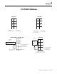
Chapter 1 1732 ArmorBlock I/O 1732D-8CFGM12 1732D-8CFGM8 Self-configuring Connector (view into connector) Self-configuring Connector (view into connector) Pin 1 Pin 2 Pin 3 Pin 4 Pin 5 Sensor Source Voltage Input or Output B Return Input or Output A Not Used 1732D-IB8M12 Pin 1 Sensor Source Voltage Pin 3 Return Pin 4 Input or Output 1732D-IB8M8 Input Micro-Connector (view into connector) Pin 1 Pin 2 Pin 3 Pin 4 Pin 5 Sensor Source Voltage Input B Return Input A Not used 1732D-OB8EM12 Input Pi
1-2 1732 ArmorBlock I/O 1732P-8CFGM12 1732P-8CFGM8 Self-configuring Connector (view into connector) Self-configuring Connector (view into connector) Pin 1 Pin 2 Pin 3 Pin 4 Pin 5 Sensor Source Voltage Input or Output B Return Input or Output A Not Used 1732P-IB8M12 Pin 1 Sensor Source Voltage Pin 3 Return Pin 4 Input or Output 1732P-IB8M8 Input Micro-Connector (view into connector) Pin 1 Pin 2 Pin 3 Pin 4 Pin 5 Sensor Source Voltage Input B Return Input A Not used 1732P-OB8EM12 Input Pico-Conn
Chapter 2 1734 POINT I/O Modules 1734-232ASC Tx S+ Rx 2 NC 7 NC NC 4 5 NC 3 S- NC 4 NC 2 3 NC 1 0 1 0 6 1734-485ASC 6 SG Tx = Transmit NC = No Connection 5 Rx = Receive SG = Signal Ground 0 Tx, S+ = Transmit NC = No Connection CG = Chassis Ground NC 2 Do not connect 120/240V ac power to this supply. Chas Chas Gnd Gnd 4 V dc 3 5 C C V V 6 7 This dc supply will be connected to the internal power bus.
2-2 1734 POINT I/O Modules 1734-FPD (12/24V dc) 0 1 NC 2 0 NC Chas Chas Gnd Gnd 4 3 Chas Chas Gnd Gnd This dc supply will be connected to the internal power bus.
1734 POINT I/O Modules 1734-IE2C 0 In 0 2 4 6 In 0 In 1 1734-IE2V Voltage Input 1 In 1 0 Chas Chas 3 Gnd Gnd C V 2 0 0 1 Aret B Bret Z Zret 3 2 5 4 6 Chas 7 Gnd Chas Gnd 0 V V Aret B Bret Z Zret 3 5 Chas Gnd Chas 7 Gnd 1734-IR2 3 NC 0 Ch 1 2 NC 4 2 Prox 3-wire RTD 5 L2/N L2/N L1 7 A, B, Z, Aret, Bret, and Zret = inputs Chas Gnd = Chassis Ground 1 Ch 0 Ch 0 = Channel 0 input NC = No connection L1 = 220V ac C 1 A 1734-IM2 L1 C V = 12/24V dc, C
2-4 1734 POINT I/O Modules 1734-IT2I 1734-IV2 Source Input 0 1 In 0 In 1 NC NC C C V V 3 Shield 4 0+ = Input Channel 0 High 0- = Input Channel 0 Low 1+ = Input Channel 1 High 1- = Input Channel 1 Low 5 0+ 4 2-Wire 7 1+ 1- 5 6 V = 12/24V dc, C = Common 12/24V dc is supplied through the internal power bus 3-Wire Prox 2-Wire Prox 2 1734-IV8 3-wire 1 In 0 In 2 In 1 In 3 4 3 5 C 1 In 0 3-Wire Prox Prox Prox 3-wire Prox V 2-wire Prox V = 12/24V dc, C = Common 12/24V
1734 POINT I/O Modules 1734-OA2 0 2 Load 1734-OB2 1 Ch 0 Ch 1 NC NC 4 0 1 Out 0 Out 1 2 3 3 Out 0 Out 1 Load Load 5 L2/N 4 L2/N 7 L1 L1 C C V V 1734-OB2E, -OB2EP 1734-OB4 0 Out Load 4 0 C V V 6 2 Load Load Load 4 6 V = 12/24V dc, C = Common Field power is supplied from the internal power bus Module power is supplied from the internal power bus 2 Load Load Out 1 1 Out 2 Out 3 3 4 5 C C C C Load 7 0 Load Load Load 1 Out 0 Out 1 Out 2 Out 3 Out
2-6 1734 POINT I/O Modules 1734-OB8E 1734-OE2C 0 Load 1 Out 0 Out 1 Out 2 Out 3 2 Load Load 3 0 Current Output Device ac or dc Load 2 4-wire 4 Load 5 Out 2 6 Load Out = Output channel Chas Gnd = Chassis ground V = Not used C = Common 7 Out 2 Load Out 3 C 6 1 Out 1 C C V V Current Output Device 3 Chas Chas Gnd Gnd 4 Load Out 3 Out 0 2-wire 5 7 C Common must be daisy chained from a 1734 adapter, 1734-FPD, 1734-EP24DC, or from a user-supplied auxiliary terminal blo
1734 POINT I/O Modules 1734-OW2 Load Powered by Internal Power Bus 0 2 Load Out 0A Out 1A Out 0B Out 1B 4 1 1734-OW4 Load Powered by External Power Bus Load Out 0A Out 1A Load 3 Out 0B Out 1B 4 Power Supply C Load 7 V V Load 5 Power Supply Out 2A Out 3A 6 6 Power Supply 1 0 Power Supply 2 3 5 C 2-7 7 Out 2B Out 3B Load Out = Output channel relay contacts Out = Output channel relay contacts V = Supply (can range from +5V dc to 240V ac) C = Common Supply voltage can ra
2-8 1734 POINT I/O Modules 1734-PDN (12/24V dc) 0 1 NC 2 0 NC Chas Chas Gnd Gnd 4 C 6 4 V ac 7 V 5 L2/N 6 V 7 L1 NC = No Connection Chas Gnd = Chassis Ground C = Common V = 12/24V dc L2/N Module 1 2 A Aret B Bret Z Zret Out 0 Out 1 3 4 6 5 7 0 2 RET 1 2 5 -Vaux -Vaux 4 +Vaux +Vaux 3 7 Publication CIG-WD001B-EN-P - May 2005 I1 C+ C- D = Data C = Clock 0 RET 0 A, B, Z, Aret, Bret, and Zret = inputs Chas Gnd = Chassis Ground -Vaux = Auxiliary Supply +Vaux
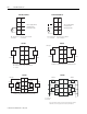
Chapter 3 1734D POINTBlock I/O Modules 1734D-IA16, -IA16S 120V ac Power Field Power 0 V ac NC 3 NC NC 4 5 6 1 4 7 6 6 7 L1in L1in L1 L1 4 L2 7 L1 L1 7 0 L1 L1 L2 6 L1 L1 L1 = 120V ac L2 = Return NC 3 NC NC 4 5 2 6 7 1 Repeat for RTB 2, 3, and 4 Outputs 2 3 L2 6 L1in L1in L1 6 L2 L1 7 L2 0 1 7 L2 2 In 3 Prox Prox 4 5 5 L2 L2 L1 L1 L2 L2 6 7 L2 3 In 2 7 6 6 L2 5 3 4 L2 L2 6 L1 2 5 In 1 1 4 3 2 L2 0 1 3 4 7 L1 1 0 2
3-2 1734D POINTBlock I/O Modules 1734D-IA8XOA8, -IA8XOA8S Output 0 1734D-IA8XOW8, -IA8XOW8S 120V ac Power 1 Out 0 Out 1 Field Power 0 2 Out 2 Out 3 Load 4 6 L2 L2 L2 3 NC NC 4 5 6 1 2 7 3 L2 L2 7 L2 L1 0B L2 L1 1B 2A L1 5A 3 4B 4 3A 5B 5 6A 6 7 2B 1 4A 2 5 6 7 0 1A 3 4 5 6 L1in L1in L1 L1 = 120V ac L2 = Return 6 7 1 0A 2 3 4 5 6 5 2 2 0 1 4 3 4 Outputs 0 1 0 L2in L2in V ac 7 NC 2 Load 5 L2 0 1 NC 3 Inputs 3B 7A 7 6B
1734D POINTBlock I/O Modules 1734D-IB8XOB8E, -IB8XOB8ES / Inputs Power 1734D-IB8XOB8E, -IB8XOB8ES Sink Input Outputs 0 1 In 0 0 1 NC 2 V dc 0 NC NC NC 4 5 Cin 6 1 2 3 3 3 Cin 5 C 5 6 7 2 C 2 4 C 6 1 3 C 6 C 3-wire 2-wire 7 Prox Prox 6 Power Field 0 3 4 5 C Load 7 C C V dc V = 12/24V dc, C = Common Field power is supplied from internal power bus 0 1 2 2 3 NC NC 4 5 6 4 7 C C 6 NC NC 2-wire C C V = 12/24V dc C = Common V V 7 5B
3-4 1734D POINTBlock I/O Modules Notes: Publication CIG-WD001B-EN-P - May 2005
Chapter 4 1738 ArmorPoint 1738-232ASCM12 1738-485ASCM12 (view into connector) Pin 1 Tx Pin 2 Tx + Pin 3 Rx + Pin 4 Rx Pin 5 No Connect (view into connector) Pin 1 Pin 2 Pin 3 Pin 4 Pin 5 No Connect Tx + Rx + Common No Connect 1738-ACNR 1738-ADN12 Male In Connector (view into connector) Pin 1 Pin 2 Pin 3 Pin 4 - User Power + Adapter Power + Adapter Power User Power - Male In Connector Female Out Connector (view into connector) Pin 1 Drain Pin 2 +V Pin 3 -V Pin 4 CAN_High Pin 5 CAN_Low DeviceNet
4-2 1738 ArmorPoint 1738-ADN18 1738-ADN18P Male In Connector Male In Connector (view into connector) Pin 1 Pin 2 Pin 3 Pin 4 Pin 5 Female Out Connector (view into connector) Pin 1 Drain Pin 2 +V Pin 3 -V Pin 4 CAN_High Pin 5 CAN_Low Drain +V -V CAN_High CAN_Low DeviceNet Auxiliary Power DeviceNet Auxiliary Power Male In Connector Male In Connector (view into connector) Pin 1 User Power + Pin 2 Adapter Power + Pin 3 Adapter Power Pin 4 User Power - (view into connector) Pin 1 User Power + Pin 2 Ada
1738 ArmorPoint 1738-APB 4-3 1738-EP24DC Male In Connector Female In Connector (view into connector) Pin 1 +5VBUS Pin 2 A-Line Pin 3 GNDBUS Pin 4 B-Line! Pin 5 Shield Male In Connector (view into connector) Pin 1 User Power + Pin 2 Adapter + Pin 3 Adapter Pin 4 User Power - Male Auxiliary Male In connector ((view into connector) Pin 1 User Power Pin 2 Adapter Power Pin 3 Protective GND Pin 4 Adapter Power + Pin 5 User Power + IMPORTANT Profibus Adapter Network connections have earth grounded metal
4-4 1738 ArmorPoint 1738-IB2M12 1738-IB4M12 (view into connector) Pin 1 24V dc Pin 2 No Connect Pin 3 Common Pin 4 Input 0 (M12-A) Input 1 (M12-B) Input 2 (M12-C) Input 3 (M12-D) Pin 5 No Connect (view into connector) Pin 1 24V dc Pin 2 No Connect Pin 3 Common Pin 4 Input 0 (M12-A) Input 1 (M12-B) Pin 5 No Connect 1738-IB4M8 1738-IB8M12 (view into connector) Pin 1 24V dc Pin 2 I nput 1 (M12-A) Input 3 (M12-B) Input 5 (M12-C) Input 7 (M12-D) Pin 3 Common Pin 4 Input 0 (M12-A) Input 2 (M12-B) Input 4 (M
1738 ArmorPoint 1738-IJM23 1 8 9 7 2 10 12 6 3 11 4 5 1738-IR2M12 (view into connector) (view into connector) Pin 1 Pin 2 Pin 3 Pin 4 Pin 5 Pin 6 Pin 7 Pin 8 Pin 9 Pin 10 Pin 11 Pin 12 Pin 1 Pin 2 +A ~A +B ~B +Z ~Z Chassis Chassis Return (Com) Return (Com) 5V dc Chassis Pin 3 Pin 4 Pin 5 IMPORTANT IMPORTANT Analog and specialty modules have earth grounded metal rings. This should be considered when choosing shielded cables and grounding techniques.
4-6 1738 ArmorPoint 1738-IV8M8 1738-OA2M12AC3 (view into connector) Pin 1 24V dc Pin 4 Input 0 (M8-A) Pin 3 Common Input 1 (M8-B) Input 2 (M8-C) Input 3 (M8-D) Input 4 (M8-E) Input 5 (M8-F) Input 6 (M8-G) Input 7 (M8-H) (view into connector) Pin 1 Chassis Pin 2 L2/N Pin 3 Output 0 (M12-A) Output 1 (M12-B) 1738-OB2EM12 1738-OB2EPM12 (view into connector) Pin 1 24V dc Pin 2 No Connect Pin 3 Common Pin 4 Output 0 (M12-A) Output 1 (M12-B) Pin 5 No Connect (view into connector) Pin 1 24V dc Pin 2 No Con
1738 ArmorPoint 1738-OB8EM8 1738-OE2CM12 (view into connector) Pin 1 24V dc Pin 3 Common Pin 4 Output 0 (M8-A) Output 1 (M8-B) Output 2 (M8-C) Output 3 (M8-D) Output 4 (M8-E) Output 5 (M8-F) Output 6 (M8-G) Output 7 (M8-H) (view into connector) Pin 1 Pin 2 Pin 3 Pin 4 Pin 5 IMPORTANT 1738-OE2VM12 Pin 2 Pin 3 Pin 4 Pin 5 IMPORTANT Output 0 (M12-A) Output 1 (M12-B) 24V dc Common Common No Connect Analog and specialty modules have earth grounded metal rings.
4-8 1738 ArmorPoint 1738-SSIM23 1738-VHSC24M23 (view into connector) 1 8 9 7 2 10 12 6 3 11 4 IMPORTANT 5 Pin 1 Pin 2 Pin 3 Pin 4 Pin 5 Pin 6 Pin 7 Pin 8 Pin 9 Pin 10 Pin 11 Pin 12 Data + Data V+ VShield Input 0 Clock + Clock Return (Com) Return (Com) 24 V dc Chassis Analog and specialty modules have earth grounded metal rings. This should be considered when choosing shielded cables and grounding techniques.
Chapter 5 1746 I/O Modules 1746-BLM Desc riptio n 14 40 2 : : : : : : : : : : : : : : : : : : : : 1 39 1492-IFM40F + 13 16 40 2 15 1 39 Axis 1 Axis 2 Axis 3 Axis 4 Dig ital OUT+ (+24EXT ) 17 18 13 14 9 10 5 6 Digit al I N- 19 15 11 7 Digit al I N+ 20 16 12 8 Re se rve d Digit al O UT- - digital output sync output + 24V EXT + digital input start-of-drop trigger - dc common 22 + 24V dc supply 21 - 4, 3, 2, 1 -24V dc RET 21 +24V dc EX T 22 An al og OUT- (GND) 23 27 3
5-2 1746 I/O Modules 1746-HSCE Differential Encoder cab le (1) + V DC COM VS GN D Input and Output Connections Power Supply Belden 9503 or equivalent 305m (1000ft) max length Upper Retaining Screw Maximum Torque = 0.7 to 0.9 Nm (6 to 8 in-lbs) Allen-Bradley 845H Series differential encoder Discrete Output Wiring The user must supply the external VDC. A A(+) A A(-) B B(+) B B(-) Z Z(+) Z(-) Z Shie ld (2) Terminal Wiring max. #14 AWG (2mm2) max. 2 wires per terminal max. torque: 0.
1746 I/O Modules 5-3 1746-HSCE Limit Switch (24V dc Hard Contact) Input and Output Connections Hard Contact Limit Switch LS (24V dc) VS LS (12V dc) + 24V dc 1746-HSCE module LS (5V dc) CO M LS COM Do not connect LS (5V dc) or LS (12V dc) Terminals 321 Jumper placed for 10 ms filtering JW 1 Connect only one LS input range at a time, or the module will be damaged.
5-4 1746 I/O Modules 1746-HSCE Outputs Input and Output Connections 1746-HSCE module VDC OUT 0 User Supplied 24V dc + OUT 1 - OUT 2 All switches OFF ON OUT 3 DC COM 1 234 OFF Dip Switch SW2 wiring terminals Do not use incandescent lamps as output indicators. The high peak inrush current required to heat the filament can damage the module’s output circuits. Use LED type indicators that satisfy the output circuit ratings, such as Allen-Bradley 800A and 800T LED indicators.
1746 I/O Modules 5-5 1746-HSCE Single-Ended Encoder (Open-Collector) Input and Output Connections cable (1) VS GN D + V DC CO M Power Supply (3) R Allen-Bradley 845H Series differential encoder Shield (2) A A(+) A(-) B B(+) B(-) Z(+) Z(-) Z ON Belden 9503 or equivalent 305m (1000tft) max length SW1 encoder connector housing 1 234 OF F (All switches OFF) Earth Module Inputs (1) Refer to your encoder manual for proper cable type and length.
5-6 1746 I/O Modules 1746-HSCE2 – Differential Encoder Cabl e (1) Input and Output Connections +VDC VS GND COM A A(+) A A(–) B B(+) B B(–) Z Z(+) Power S upply Release screw A1 + A1 - B1 + B1- Z1+ Z1- A2 + Allen-Bradley 845H Series differential encoder A2- B2 + B2 - Z2+ Shi e ld Z2- Output common shield/housing Connect only if housing is electronically isolated from the motor and ground.
1746 I/O Modules 5-7 1746-HSCE2 Single-Ended (Discrete Devices) +VDC Input and Output Connections COM Release screw A1 + B1 + proximity sensor A1 - VS A2 + Z2+ Output common OUTPUT 1 OUTPUT 3 Release screw VS solid-state switch A2- OUT B(+) COM B(–) VS B2 - OUT Z2- OUTPUT 2 A(–) COM Z1- OUTPUT 0 A(+) OUT B1- Z1+ B2 + Power S uppl y R (1) Z(+) COM Z(–) photoelectric sensor with open collector sinking output +V dc Module Inputs 1.
5-8 1746 I/O Modules 1746-HSRV – Wiring a 15V Encoder ENCODER C H A. HI A 1 CH A. LO A AB SHLD CH B. HI B 1 CH B. LO B Z SHLD CH Z. HI B Z 1 CH Z. LO I C J Z ENCODER POWER +5 V A 3 Optical Encoder G F D +15V Return 2 RET Case Ground +1 5 V SHLD +15V 1 Use three pair 22 gauge individually twisted and shielded cable. 2 Use one pair 18 gauge twisted and shielded cable.
1746 I/O Modules 5-9 1746-HSRV – Wiring a 5V Encoder ENCODER C H A. HI A 1 CH A. LO A AB SHLD CH B. HI B 1 CH B. LO B Z SHLD CH Z. HI Z 1 CH Z. LO Z ENCODER POWER +5 V I H B A 3 Optical Encoder C J F D G +5V 2 RET +1 5 V +5V Return SHLD Case Ground 1 Use three pair 22 gauge individually twisted and shielded cable. 2 Use one pair 18 gauge twisted and shielded cable.
5-10 1746 I/O Modules 1746-HSTP1 – Wiring a 15V Encoder 7-24V DC user power (1) CW + or non directional pulse output (2) CW - or non directional pulse output (3) CW + pulse or direction signal output (4) CCW - pulse or direction signal output (5) External interrupt input (6) Home limit switch input (7) Home Proximity limit switch input (8) CW limit switch input (9) 1 CCW limit switch input (10) A A Pulse train enable/disable input (11) 1 A Hi (Loopback + non directional pulse) (12) B H A Lo (Loopba
1746 I/O Modules 1746-IA16 1746-IA4 1746-IA8 100/120V ac 100/120V ac L1 100/120V ac NOT USED IN 0 0 1 IN 2 2 3 IN 5 6 IN 7 IN 3 L1 10 IN 9 12 IN 1 1 IN 4 IN 1 IN 5 11 IN 10 100/120V ac IN 2 IN 6 13 IN 12 14 IN 13 16 IN 15 IN 3 IN 7 15 IN 14 L2 AC COM 17 L2 AC COM L2 AC COM AC COM COMMONS CONNECTED INTERNALLY COMMONS CONNECTED INTERNALLY SLC (decimal) PLC (octal) 1746-IB16 24V dc sinking 24V dc Sinking 0 IN 1 1 IN 2 2 IN 3 3 IN 4 dc Com 1(2) COM 1 COM 3 dc
5-12 1746 I/O Modules 1746-IB8 1746-IC16 24V dc Sinking 48V dc Sinking +DC +DC IN 0 IN 0 IN 1 IN 2 0 IN 1 1 IN 3 2 IN 2 3 IN 4 48V dc IN 3 24V dc IN 4 4 IN 5 5 IN 6 6 IN 7 IN 8 6 10 IN 9 IN 5 IN 10 IN 6 IN 12 12 IN 1 1 IN 7 COMMONS CONNECTED INTERNALLY 15 16 IN 15 17 DC COM -DC 13 IN 13 14 IN 14 DC COM -DC 7 11 DC COM DC COM COMMONS CONNECTED INTERNALLY SLC (decimal) PLC (octal) 1746-IG16 1746-IH16 125V dc Sinking TTL Input (Low = True) +DC +5 DC 1 0 IN 0 2 I
1746 I/O Modules 1746-IM16 1746-IM4 200/240V ac 200/240V ac 1746-IM8 200/240V ac L1 NOT USED IN 0 0 IN 1 2 IN 3 1 IN 2 3 IN 4 4 IN 5 6 IN 7 10 IN 9 12 IN 1 1 14 IN 13 16 IN 15 L1 IN 1 NOT USED IN 2 L1 IN 3 200/240V ac IN 0 IN 4 7 IN 8 IN 1 IN 5 11 IN 10 200/240V ac IN 2 IN 6 13 IN 12 IN 3 IN 7 15 IN 14 L2 AC COM L2 17 L2 IN 0 NOT USED NOT USED 5 IN 6 200/240V ac 5-13 AC COM COMMONS CONNECTED INTERNALLY AC COM COMMONS CONNECTED INTERNALLY AC COM
5-14 1746 I/O Modules 1746-IO12 1746-IO12DC 24V dc INPUT - RELAY OUTPUT 100/120V ac INPUT - RELAY OUTPUT L1 or +DC L1 or +DC VAC-VDC VAC-VDC OUT 0 OUT 0 OUT 1 V ac/dc OUT 1 OUT 2 V ac/dc OUT 3 OUT 4 OUT 5 CR OUT 2 OUT 3 OUT 4 CR CR NOT USED OUT 5 CR NOT USED L2 or -DC L2 or -DC +DC L1 NOT USED NOT USED IN 0 IN 0 IN 1 IN 1 IN 2 IN 2 IN 3 100/120V ac 10-30V dc IN 3 IN 4 IN 4 IN 5 IN 5 NOT USED L2 NOT USED NOT USED NOT USED AC COM DC COM -DC 1746-IO4 1746-IO8 174
1746 I/O Modules 1746-ITV16 5-15 1746-IV16 24V dc Sourcing 24V dc Sourcing -DC -DC IN 0 IN 2 0 IN 1 2 IN 3 4 IN 5 IN 6 6 IN 8 IN 10 +DC 24V dc IN 8 IN 9 12 IN 1 1 14 IN 13 16 IN 15 IN 1 2 IN 3 4 IN 5 1 3 IN 6 IN 7 10 0 IN 4 5 7 IN 12 IN 14 IN 2 3 IN 4 24V dc IN 0 1 11 IN 10 13 IN 12 15 IN 14 17 +DC VDC 6 IN 7 10 IN 9 5 7 11 12 IN 1 1 14 IN 13 13 15 16 IN 15 17 VDC VDC VDC VDC CONNECTED INTERNALLY VDC CONNECTED INTERNALLY SLC (decimal) SLC (d
5-16 1746 I/O Modules 1746-NI16I (2) Channel 0 2-Wire Current Transmitter + - + IN 0 IN 1 IN 2 IN 3 Terminal Block Spare Part Catalog Number 1746-RT25G (2) + Channel 2 2-Wire Current Transmitter Channel 4 2-Wire Current Transmitter Channel 6 3-Wire Current Transmitter Vdc power supply(5) + + Channel 2 (2) + IN 4 IN 5 Channel 3 Channel 5 Channel 6 (2) + Channel 1 Channel 4 + IN 6 Channel 7 IN 7 Analog Com Analog Com Channel 8 - ANALOG ANALOG (1) COM COM (1) Channel 10 Chann
1746 I/O Modules 5-17 1746-NI16V (2) Channel 0 Voltage Transmitter Channel 2 Voltage Transmitter + + – Channel 6 Voltage Transmitter Vdc power supply(5) IN 1 + + IN 2 IN 3 IN 4 IN 5 Terminal Block Spare Part Catalog Number 1746-RT25G – Channel 0 (2) Channel 4 Voltage Transmitter IN 0 (2) + Channel 2 + Channel 1 Channel 3 Channel 4 – (2) + IN 6 Channel 5 IN 7 Channel 6 Channel 7 + Analog Com ANALOG ANALOG (1) – COM COM (1) – + IN 8 IN 9 (3) – Analog Com Channel 8 Ch
5-18 1746 I/O Modules 1746-NI8 Terminal Block Spare Part Catalog Number 1746-RT25G shield Power + Supply Connections – single-end signal source + + + + shield + + shield – + – + – Channel 2 Channel 3 (+) Channel 3 (-) Channel 4 (+) Channel 3 Channel 5 (+) Channel 5 (-) – Channel 6 (+) Channel 6 (-) + + differential signal source – Channel 4 – shield + Channel 7 (+) Channel 7 (-) Shield Channel 5 Terminal Block Release Screw Maximum Torque=0.7 to 0.9 Nm (6 to 8 in-lbs.
1746 I/O Modules 1746-NO4I 24V dc power supply if external power is selected. Cable length from external 24V dc power supply to analog module must be less than 10m. 1746-NO4V Ext. pwr sup. LOAD earth ground LOAD Analog commons are internally connected in the module. Channels are not isolated from each other. earth ground Do not jumper unused outputs. 0 1 +24V dc dc COM 0 1 2 3 4 5 6 7 OUT 0 ANL COM 24V dc power supply if external power is selected.
5-20 1746 I/O Modules 1746-NR4 Terminal Connections Release Screw Max Torque = 0.7 - 0.9 Nm (6 - 8 in-lbs) Shield Shield Channel 0 RTD Channel 1 RTD Channel 0 Sense Channel 1 Sense Channel 0 Return Channel 1 Return Shield Shield Channel 2 RTD Channel 3 RTD Channel 2 Sense Channel 3 Sense Channel 2 Return Channel 3 Return Shield Shield Release Screw Max Torque = 0.7 - 0.
1746 I/O Modules 5-21 1746-NR8 Terminal Connections 2-Wire RTD Cable Shield (Frame Ground) 2-Wire Potentiometer Add Jumper RTD 0 Sense 0 Return 0 RTD 1 Sense 1 Return 1 RTD 2 Sense 2 Return2 RTD RTD 0 Sense 0 Return 0 RTD 1 Sense 1 Return 1 RTD 2 Sense 2 Return2 RTD 3 Sense 3 Return 3 RTD 4 Sense 4 Return 4 RTD 5 Sense 5 Return 5 RTD 6 Sense 6 Return 6 RTD 7 Sense 7 Return 7 Return Belden #9501 Shielded Cable 3-Wire RTD Cable Shield (Frame Ground) RTD 0 Sense 0 Return 0 RTD 1 Sense 1 Return 1 RT
5-22 1746 I/O Modules 1746-OA8 1746-OA16 100 to 240V ac Triac Output 100 to 240V ac Triac Output L1 VAC 1 100-240V ac 5 OUT 6 CR 6 OUT 7 CR OUT 3 CR CR 4 CR CR OUT 2 1 2 OUT 5 100-240V ac CR OUT 3 11 OUT 8 13 OUT 10 100-240V ac 15 OUT 12 14 OUT 15 CR CR OUT 6 17 OUT 14 16 CR OUT 7 L2 CR NOT USED L2 L2 100-240V ac 12 OUT 13 CR 2 4 10 OUT 1 1 OUT 4 OUT 5 L1 VAC 2 OUT 9 L1 VAC 2 0 5 OUT 4 NOT USED 7 L2 OUT 0 3 OUT 2 OUT 5 L2 CR VAC 1 OUT 1 1 OUT 2
1746 I/O Modules 1746-OB32 1746-OB32E 5 to 50V dc Transistor Output Sourcing 10 to 30V dc Electronically Protected Sourcing Wire Group 2 Wire Group 1 VDC 1 VDC 2 +V dc 2(2)(3) +V dc 1 +V dc 1 (2)(3) VDC 1 VDC 2 +V dc 2(2)(3) +V dc 1 (2)(3) 0 1 2 2 CR 2 CR 10 OUT 13 CR OUT 28 14 OUT 13 15 OUT 29 OUT 14 16 16 15 OUT 30 16 16 OUT 31 OUT 15 17 17 14 15 OUT 30 dc Com 1(2) COM 1 COM 2 dc Com 2(2) dc Com 1(2) COM 1 COM 2 dc Com 2(2) OUT 31 17 17 dc Com 1(2) dc Com 1 (
5-24 1746 I/O Modules 1746-OBP16 1746-OBP8 20.4 to 26.4V dc Transistor Output-Sourcing Transistor Output-Sourcing 1 +DC VDC 1 OUT 2 3 OUT 4 5 OUT 6 7 OUT 8 11 OUT 10 13 OUT 12 15 OUT 14 CR OUT 3 20.4-26.4V dc DC COM1 NC NC NC CR -DC CR 12 OUT 1 1 14 OUT 13 CR OUT 1 6 10 OUT 9 CR OUT 2 4 OUT 7 20.4-26.4V dc OUT 0 2 OUT 5 CR VDC1 0 OUT 3 CR +DC OUT 0 OUT 1 16 OUT 15 CR NC CR NC NC CR +DC VDC2 17 OUT 4 DC COM CR OUT 5 CR OUT 7 OUT 6 20.4-26.
1746 I/O Modules 1746-OV8 1746-OV32 5 to 50V dc Transistor Output Sinking +V dc 1(2) VDC 1 VDC 2 +V dc 2(2) VDC VDC 1 VDC 2 +V dc 2(2) OUT 0 1 OUT 19 3 CR 5 OUT 5 CR 6 OUT 6 OUT 21 5 OUT 22 OUT 6 6 OUT 23 OUT 7 OUT 24 OUT 25 11 OUT 10 11 OUT 27 13 OUT 12 -DC CR 12 12 OUT 1 1 CR DC COM CR OUT 26 CR OUT 7 CR 10 10 OUT 9 CR 7 7 OUT 8 CR CR 13 OUT 28 14 OUT 13 14 OUT 29 15 15 OUT 14 OUT 30 16 16 OUT 31 OUT 15 17 17 dc Com 1 10-50V dc OUT 4 4 4 (2)(3) O
5-26 1746 I/O Modules 1746-OW4 1746-OW8 Relay Output 1746-OX8 Channel-to-Channel Isolated Relay Output Relay Output L1 or +DC VAC-VDC 1 L1 or +DC VAC-VDC OUT 0 OUT 0 V ac/dc OUT 1 V ac/dc OUT 1 CR OUT 2 L2 or -DC CR OUT 3 CR OUT 2 NOT USED VAC-VDC 2 NOT USED OUT 4 NOT USED VS1 L1 VAC-VDC 1 VS2 VDC VAC-VDC 2 VS3 VDC VAC±VDC 3 NOT USED L1 or +DC VS4 L1 VAC-VDC 4 VS5 L1 VAC-VDC 5 OUT 0 V ac/dc OUT 6 CR OUT 7 CR L2 or -DC VS6 VDC VAC-VDC 6 VS7 VDC VAC-VDC 7 (+) 9
Chapter 6 1747 I/O on Fixed Hardware Controllers 1747-L20A (Hi) L1 (Lo) L2 5-265 V AC or 5-125 VDC 1 1747-L20B (Hi) L1 1 CR CR (Hi) L1 (Lo) L2 5-265 V AC or 5-125 VDC 85-265 V AC CR (Lo) L2 (Lo) L2 (Hi) L1 85-132 V AC CHASSIS GND NOT USED NOT USED AC COM AC COM IN 0 IN 1 IN 3 IN 2 IN 5 IN 4 IN 7 IN 6 IN 9 IN 8 IN 11 IN 10 Commons Connected Internally The outputs are isolated in groups as shown.
6-2 1747 I/O on Fixed Hardware Controllers 1747-L20C (Hi) L1 5-265 V AC 5-125 VDC 1747-L20F (Hi) L1 (Lo) L2 1 5-265 V AC 5-125 VDC 1 CR (Hi) L1 (Lo) L2 CR CR 5-265 V AC or 5-125 VDC 1 (Hi) L1 CR (Lo) L2 5-265 V AC or 5-125 VDC 1 CR CR CR CR VAC OUT 0 OUT 1 OUT 2 OUT 3 VAC OUT 4 OUT 5 OUT 6 OUT 7 VDC 1 VDC 2 VAC OUT 0 OUT 1 OUT 2 OUT 3 VAC OUT 4 OUT 5 OUT 6 OUT 7 VDC 1 VDC 2 (Hi) L1 (Lo) L2 (Lo) L2 - DC + DC 10-30 VDC + - 85-265 VAC Sourcing Device 120/240 VAC VAC NEUT CHASSI
1747 I/O on Fixed Hardware Controllers 6-3 1747-L30B (Hi) L1 (Hi) L1 (Lo) L2 85-265 V AC (Lo) L2 85-265 V AC 1 CR CR CR VAC 1 VAC 1 OUT 0 OUT 1 OUT 2 OUT 3 OUT 4 OUT 5 NOT USED NOT USED 1 CR CR VAC 2 VAC 2 OUT 6 OUT 7 OUT 8 VAC 1 Connected Internally OUT 9 CR OUT 10 OUT 1 1 NOT USED NOT USED VAC 2 Connected Internally (Hi) L1 (Lo) L2 (Lo) L2 (Hi) L1 85-132 V AC 85 - 265 VAC 120/240 VAC NEUT VAC CHASSIS GND NOT USED NOT USED AC COM AC COM AC COM AC COM IN 1 IN 0 IN 3 IN 2
6-4 1747 I/O on Fixed Hardware Controllers 1747-L40A (Hi) L1 5-265 V AC 5-125 VDC (Hi) L1 (Lo) L2 1 1 CR (Hi) L1 (Lo) L2 5-265 V AC 5-125 VDC CR CR 5-265 V AC 5-125 VDC (Hi) L1 (Lo) L2 CR CR (Lo) L2 5-265 V AC 5-125 VDC 1 1 CR CR CR VAC OUT 0 OUT 1 OUT 2 OUT 3 VAC OUT 4 OUT 5 OUT 6 OUT 7 VAC OUT 8 OUT 9 OUT 10 OUT 1 1 VAC OUT 12 OUT 13 OUT 14 OUT 15 VDC 1 VDC 2 VDC 3 VDC 4 (Hi) L1 (Lo) L2 (Lo) L2 (Hi) L1 85-132 V AC 85-265 VAC 120/240 VAC VAC NEUT CHASSIS GND NOT USED NOT US
1747 I/O on Fixed Hardware Controllers 6-5 1747-L40C (Hi) L1 5-265 V AC 5-125 VDC (Hi) L1 (Lo) L2 1 1 CR (Hi) L1 (Lo) L2 5-265 V AC 5-125 VDC CR CR (Hi) L1 (Lo) L2 5-265 V AC 5-125 VDC 5-265 V AC 5-125 VDC 1 CR CR CR (Lo) L2 1 CR CR VAC OUT 0 OUT 1 OUT 2 OUT 3 VAC OUT 4 OUT 5 OUT 6 OUT 7 VAC OUT 8 OUT 9 OUT 10 OUT 1 1 VAC OUT 12 OUT 13 OUT 14 OUT 15 VDC 1 VDC 2 VDC 3 VDC 4 Sourcing Device (Hi) L1 (Lo) L2 85-265 VAC 120/240 VAC VAC NEUT CHASSIS GND PWR OUT DC +24VDC 2 COM PWR OU
6-6 1747 I/O on Fixed Hardware Controllers 1747-L40F (Hi) L1 5-265 V AC 5-125 VDC (Hi) L1 (Lo) L2 5-265 V AC 5-125 VDC 1 CR CR (Hi) L1 (Lo) L2 5-265 V AC 5-125 VDC 1 CR (Hi) L1 (Lo) L2 5-265 V AC 5-125 VDC 1 CR CR (Lo) L2 1 CR CR CR VAC OUT 0 OUT 1 OUT 2 OUT 3 VAC OUT 4 OUT 5 OUT 6 OUT 7 VAC OUT 8 OUT 9 OUT 10 OUT 1 1 VAC OUT 12 OUT 13 OUT 14 OUT 15 VDC 1 VDC 2 VDC 3 VDC 4 - DC + DC 10-30 VDC + - 24 VDC + 10 % + 24 VDC VDC NEUT NOT USED EAR TH NOT GND USED DC COM DC COM
Chapter 7 1756 ControlLogix I/O Modules 1756-CFM - Standard Flowmeter Wiring 2 1756-CFM - Standard Prover/Detector Wiring 1 12-24V dc Z0 12-24V dc Z1 12-24V dc 4 3 6 5 8 7 – F1 10 9 12 11 14 13 16 15 18 17 F0 Return Input Device F1 Return Not used Shield ground Shield ground Z1 RET F0 + 20 19 6 5 8 7 Z1 5V dc Z0 Return Z1 RET F0 F1 10 9 12 11 F0 Return F1 Return Not used Not used 14 16 15 18 17 20 19 Output 0 + Load – Customer VCC Customer VCC 11
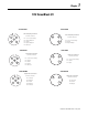
7-2 1756 ControlLogix I/O Modules 1756-HSC - 872 3-Wire DC Proximity Sensor Allen-Bradley Bulletin 872 3-Wire DC Proximity Sensor Z0 (12-24V) Jumpers Black 12-24V dc Blue 12-24V dc Return 2 1756-HSC - Photoswitch Series 10,000 Photoelectric Sensor Z1 (12-24V) 1 Z0 (5V) 4 3 Z1 (5V) Z0 (RET) 6 5 Z1 (RET) Z0 (12-24V) 2 1 Z1 (12-24V) Z0 (5V) 4 3 Z1 (5V) Z0 (RET) 6 5 Z1 (RET) Photoswitch Series 10,000 Photoelectric Sensor White Blue B0 (12-24V) 8 7 B1 (12-24V) B0 (12-24V)
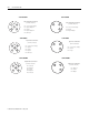
1756 ControlLogix I/O Modules 1756-HYD02 - Wiring Home Limit Switch 7-3 1756-HYD02 - Wiring OK Contacts 24V dc Field Power Supply 24V dc Field Power Supply + – + – OK Pilot Relay From 1756-HYD02 HOME IN_COM General cable C0720 +OK -OK General cable C0720 From 1756-HYD02 OK Pilot Relay Contacts CR1 Start Stop CR1 M1 24V AC/DC or 120VAC typical CR1 1756-IA16 2 1 4 3 IN-1 IN-0 Group 0 Daisy chain to other RTBs L2-0 2 1 IN-0 L2-1 4 3 IN-1 L2-2 6 5 IN-2 L2-3 8 7 IN-3 L2
7-4 1756 ControlLogix I/O Modules 1756-IA32 IN-1 IN-3 IN-5 IN-7 IN-9 IN-11 IN-13 IN-15 L2-0 IN-17 IN-19 IN-21 IN-23 IN-25 IN-27 IN-29 IN-31 L2-1 Group 0 Daisy chain to other RTBs Group 1 2 IN-0 IN-2 IN-4 IN-6 IN-8 IN-10 IN-12 IN-14 1 4 3 6 5 8 7 10 1756-IA8D 9 12 11 14 13 16 15 18 17 L2-0 IN-16 IN-18 IN-20 IN-22 IN-24 IN-26 IN-28 IN-30 L2-1 20 19 22 21 24 23 26 25 28 27 30 29 32 31 34 33 36 35 Daisy chain to other RTBs Group 0 Group 0 1 Daisy chain to other RTBs Group 1 IN-4 9 L1
1756 ControlLogix I/O Modules 1756-IB16I 1756-IB16ISOE Isolated wiring Sink input wiring DC-0 (-) DC-5 (-) – + Jumper bar (Part number 97739201) Non-isolated wiring DC (-) GND-0 2 1 IN-0 GND-1 4 3 IN-1 GND-2 6 5 IN-2 GND-3 8 7 IN-3 GND-4 10 9 IN-4 GND-5 12 11 IN-5 GND-6 14 13 IN-6 GND-7 16 15 IN-7 GND-8 18 17 IN-8 GND-9 20 19 IN-9 GND-10 22 21 IN-10 GND-11 24 23 IN-11 GND-12 26 25 IN-12 GND-13 GND-14 28 27 IN-13 30 29 IN-14 GND-15 32 31 IN-15 GN
7-6 1756 ControlLogix I/O Modules 1756-IF16 – Differential Current Applications Channel 0 i Channel 0 A Shield ground Channel 3 2-Wire Transmitter Channel 6 i A i + + A 4-Wire Transmitter 24V dc – – 1756-IF16 – Differential Voltage Applications IN-0 IN-1 IN-2 IN-3 RTN IN-4 IN-5 IN-6 IN-7 IN-8 IN-9 IN-10 IN-11 RTN IN-12 IN-13 IN-14 IN-15 2 1 4 3 6 5 8 7 10 9 i RTN-0 i RTN-1 i RTN-2 i RTN-3 RTN i RTN-4 i RTN-5 i RTN-6 i RTN-7 i RTN-8 i RTN-9 i RTN-10 i RTN-11 RTN i RTN-12 i RTN-13
1756 ControlLogix I/O Modules 1756-IF4FXOF2F Current Mode (+) (-) 1756-IF4FXOF2F Voltage Mode A (+) (+) i 2-Wire A Transmitter +IN-1/V IN-1/I -IN-1 2 1 4 3 6 5 +IN-0/V IN-0/I -IN-0 +IN-3/V 8 7 +IN-2/V User Analog Input Device (-) IN-3/I 10 9 -IN-3 Not used Not used V OUT-1 12 11 I OUT-1 RTN-1 20 19 Not used Not used 24 23 Not used Not used 28 27 30 29 Not used Not used Not used 32 31 Not used 34 33 Not used 36 35 14 13 16 15 18 17 22 21 26 25 IN-2/I -IN-2 +IN-1/V IN
7-8 1756 ControlLogix I/O Modules 1756-IF6CIS - 4-Wire transmitter connected to the module and an external, user-provided power supply providing 24V dc loop power 1756-IF6I - Current Application with 2-Wire Transmitter 1 2 VOUT-0 i 3 4 IN-1/V A IN-1/I IN-0/I 6 5 RTN-1 RTN-0 8 7 10 9 VOUT-3 A 4-Wire Transmitter – 16 15 Not used 8 Shield ground 18 10 9 12 11 14 13 16 15 18 17 20 19 IN-2/I RET-3 RET-2 Not used Not used IN-4/I 20 A 7 IN-3/I 17 19 RTN-5 IN-4/V IN-
1756 ControlLogix I/O Modules 1756-IF8 – Differential Current Applications 1756-IF8 – Differential Voltage Applications Channel 0 Channel 0 i To field device A Shield ground Channel 3 2-Wire Transmitter i A IN-0 2 1 i RTN-0 IN-1 4 3 i RTN-1 IN-2 6 5 i RTN-2 IN-3 8 7 i RTN-3 RTN 10 9 RTN IN-4 12 11 14 13 i RTN-5 IN-6 16 15 i RTN-6 IN-7 18 17 i RTN-7 Not used 20 19 Not used Not used 22 21 Not used Not used 24 23 Not used Not used 26 25 Not used Not used 28 27
7-10 1756 ControlLogix I/O Modules 1756-IG16 2 1 IN-1 6 5 8 7 IN-5 DC power wire IN-7 1 IN-0 4 3 6 5 IN-1 IN-2 IN-4 DC-3 (-) GND-3 8 7 IN-3 GND-4 GND-5 GND-6 10 9 IN-4 IN-5 IN-6 GND-7 GND-8 16 15 GND-9 GND-10 GND-11 20 19 GND-12 GND-13 26 25 GND-14 GND-15 30 29 32 31 IN-14 IN-15 GND-15 34 33 Not used Not used 36 35 Not used I/O wire IN-6 10 9 DC-0(+) DC COM 0 12 DC-7 (-) 11 IN-8 IN-9 14 13 16 15 Jumper bar (Cut to length) IN-10 IN-11 5V dc power 2 GND
1756 ControlLogix I/O Modules 1756-IN16 1756-IR6I – 2 or 3-Wire RTD 2 2 1 4 3 6 5 8 7 IN-1 IN-3 IN-5 10 9 14 IN-8 RTN-3/C IN-10 Not used 13 IN-11 16 15 18 17 IN-13 IN-12 IN-15 Group 1 20 8 7 IN-0/B RTN-0/C 3-Wire RTD IN-2/A 10 9 12 11 IN-2/B 14 13 16 15 18 17 20 19 Not used IN-4/A IN-5/B 19 L2-1 Shield Ground RTN-2/C IN-5/A IN-14 L2-1 5 IN-3/B 11 IN-9 6 IN-3/A L2-0 12 Group 1 Group 0 IN-6 L2-0 3 RTN-1/C IN-4 IN-7 IN-0/A 4 IN-1/B IN-2 Grou
7-12 1756 ControlLogix I/O Modules 1756-IT6I2 1756-IV16 Cold junction sensor Wire Spade Lug 2 1 Not used 3 6 5 CJC– CJC+ RTN-0 6 5 Group 0 IN-4 IN-5 Thermocouple + 8 7 10 9 12 11 14 13 16 15 18 17 20 19 IN-6 IN-7 DC-0 + DC-0 + IN-1 IN-8 IN-9 9 RTN-2 IN-2 12 3 IN-2 Group 0 7 RTN-1 10 4 IN-0 IN-0 8 1 IN-3 Not used 4 2 IN-1 RTN-3 Group 1 IN-3 14 13 16 15 18 17 20 19 IN-10 IN-11 – 11 RTN-4 CJC– IN-14 DC-1 + IN-5 Group 1 IN-12 IN-15 IN
1756 ControlLogix I/O Modules 1756-MO2AE – Wiring to 1394 Servo Drive (in Torque Mode only) 1756-MO2AE – Wiring to an Ultra 100 Series Drive J1 to 50-pin Terminal Block (Kit P/N 9109-1391) Servo Module RTB +OUT 1 -OUT 1 +ENABLE 1 -ENABLE 1 DRVFLT 1 CHASSIS IN_COM HOME 1 REG24V 1 REG5V 1 -OK CHASSIS +CHA 1 -CHA 1 +CHB 1 -CHB 1 +CHZ 1 -CHZ 1 +OUT 0 -OUT 0 +ENABLE 0 -ENABLE 0 DRVFLT 0 CHASSIS IN_COM HOME 0 REG24V 0 REG5V 0 +OK CHASSIS +CHA 0 -CHA 0 +CHB 0 -CHB 0 +CHZ 0 -CHZ 0 RED BLK WHT BLK RED BLK A G
7-14 1756 ControlLogix I/O Modules 1756-MO2AE – Wiring 24V Registration Sensors 24 VDC Field Power Supply + - 1756-MO2AE – Wiring 5V Registration Sensors 5 VDC Field Power Supply 24 V olt Sourcing Type Registration Sensor 5 Volt Sourcing Type Registration Sensor + - Supply Supply From 1756-M02AE General Cable C0720 REG24V Output IN_COM Common General Cable C0720 From 1756-M02AE REG5V Output IN_COM Common The registration inputs to the servo module support 24V or 5V registration sensors
1756 ControlLogix I/O Modules 1756-OA16 2 1756-OA16I Is olate d wiri ng 1 OUT-1 OUT-0 4 Group 0 OUT-2 6 5 OUT-5 OUT-4 L1-2 Group 0 L1-4 7 8 OUT-7 OUT-6 10 9 12 11 L1-0 L2-0 OUT-9 Jumper bar - Cut to length (Part number 97739201) OUT-8 14 13 OUT-11 OUT-10 16 Group 1 L1-0 3 OUT-3 Daisy chain to other RTBs 15 OUT-13 OUT-12 18 17 OUT-15 Non-isolated wiring Group 1 OUT-14 20 7-15 19 L1-1 L2-1 L1 L1-0 2 1 OUT-0 L1-1 4 3 OUT-1 L1-2 6 5 OUT-2 L1-3 8 7 OUT
7-16 1756 ControlLogix I/O Modules 1756-OA8E 2 Daisy chain to other RTBs 1 L2-0 Not used 4 3 OUT-0 L1-0 6 5 L1-0 Group 0 OUT-1 8 Group 0 OUT-2 10 9 12 11 L1-0 OUT-3 OUT-4 L1-1 14 13 L1-1 OUT-5 16 15 OUT-6 L1-1 18 17 OUT-7 L1-1 Group 1 Group 0 7 L1-0 Daisy chain to other RTBs 1756-OB16D 20 Group 1 Group 1 19 L2-1 L1-1 L2 Daisy chain to other RTBs +DC-0 2 1 OUT-0 +DC-0 4 3 OUT-1 +DC-0 6 5 OUT-2 +DC-0 8 7 OUT-3 +DC-0 10 9 OUT-4 +DC-0 12 11 OUT-5
1756 ControlLogix I/O Modules 1756-OB16IS 1756-OB32 Isolated wiring DC-0 (+) DC-1 (+) DC-2 (+) DC-2 (+) DC-3 (+) DC-4 (+) Sinking output wiring DC-5 (+) DC-6 (+) DC-6 (+) + – DC-7 (+) Jumper bar DC-8 (+) (Cut to length) DC-9 (+) DC-10 (+) DC-11 (+) Non-isolated DC-12 (+) wiring DC-13 (+) DC-14 (+) DC-15 (+) DC(+) DC-15 (+) Not used DC-0 (+) 2 1 4 3 6 5 8 7 10 9 12 11 14 13 16 15 18 17 20 19 22 21 24 23 26 25 28 27 30 29 32 31 34 33 36 35 7-17 OUT-0 OUT-1 OUT-2 OUT-3
7-18 1756 ControlLogix I/O Modules 1756-OC8 1756-OF4 – Current Applications Daisy chain to other RTBs 2 1 4 3 DC-0 (+) OUT-0 DC-0 (+) OUT-1 Group 0 6 13 Group 1 15 DC-1(+) 11 14 13 16 15 DC-1(+) 18 17 20 19 Not used IOUT-2 RTN OUT-7 RTN OUT-1 RTN Not used RTN OUT-1 Shield ground VOUT-2 OUT-6 19 12 IOUT-1 OUT-5 20 9 Not used DC-1(+) 17 10 VOUT-1 OUT-4 18 7 Not used 11 DC-1(+) 16 8 Current output load A RTN RTN OUT-0 Group 1 5 Not used 9 RTN OUT-
1756 ControlLogix I/O Modules 1756-OF6VI 1756-OF6CI – 551 - 1000Ω Applications 2 1 OUT-1 2 OUT-0 4 User Analog Output Device ALT-0 6 OUT-0 4 RTN-0 8 10 9 12 11 14 13 ALT-3 18 ALT-4 20 12 11 14 13 Not used RTN-2 16 15 18 17 20 19 OUT-4 Not used RTN-4 RTN-5 NOTES: RTN-4 1. Place additional devices anywhere in the loop. 2. Do not connect more than 2 wires to any single terminal. NO TE S: Do not connect more than 2 wires to any single terminal.
7-20 1756 ControlLogix I/O Modules 1756-OG16 1756-OH8I Isol ated W iri ng DC power wire + 5V dc power 2 – OUT-0 4 OUT-2 6 5 OUT-5 8 7 10 9 12 11 DC COM 0 OUT-9 OUT-8 14 13 16 15 OUT-11 Capacitor 0.01µ F typical (See notes below) - OUT-6 DC-0(+) – + OUT-4 OUT-7 I/O wire - 3 OUT-3 + + 1 OUT-1 Non-Isol ated Wi ri ng OUT-10 OUT-13 OUT-12 18 17 OUT-15 OUT-14 20 DC-1(+) 19 Daisy chain to other RTBs DC COM 1 GENERAL NOTES: 1.
1756 ControlLogix I/O Modules 1756-OW16I 1756-OV32E Isol ated w iring L1-0 L1-0 L1-1 L1-2 L1-2 L1-3 DC-4 (+) L1-4 L1-5 L1-6 Jumper bar - Cut to length L1-7 (Part number 97739201) L1-8 L1-9 L1-10 L1-11 Non -isol ated L1-12 wi ring L1-13 L1-14 L1-15 L1-15 L1 Not used 2 1 4 3 6 5 8 7 10 9 12 11 14 13 16 15 18 17 20 19 22 21 24 23 26 25 28 27 30 29 32 31 34 33 36 35 L2-0 OUT-0 OUT-1 N.O. OUT-2 N.O. OUT-3 N.O. OUT-4 N.O. OUT-5 N.O. OUT-6 N.O. OUT-7 N.O. OUT-8 N.O. OUT-9 N.O. OUT-10 N.O.
7-22 1756 ControlLogix I/O Modules 1756-PLS Resolver Module 2 1 Do not use Do not use 4 3 6 5 Do not use Do not use Do not use Do not use Do not use 10 9 Do not use Do not use 12 11 14 13 Do not use Do not use F ( S3) E (S2) G (S4) A White R1 B Black of white R2 1 4 ( Sine+ ) F Black of red S3 16 (S ine-) D Red S1 18 (Cosine+) E Green S2 20 (Cosi ne- ) G Black of green S4 17 (Refere nce+) 19 (Reference-) Do not use Sine + D (S1) Resolver Signal Name 846-SJx
Chapter 8 1761 Controller I/O on MicroLogix 1000 Controllers 1761-L10BWA Sinking Input Configuration Sourcing Input Configuration 14–30V dc VDC (–) VDC + 14–30V dc VDC (+) DC OU T DC CO M I/0 I/1 I/2 I/3 DC CO M I/4 VAC VDC O/2 VDC I/5 VAC VAC VDC L2/N O/0 VDC O/1 + 24V – NO T NO T NO T NO T US ED US ED US ED US ED 85–264 VAC L1 VDC (–) for Sourcing VDC (–) + 24V – VDC (+) VDC (–) for Sourcing VDC (+) NO T VAC NO T DC OU T I/0 I/1 VAC VDC L2/N L1 CR VAC 2 VDC 1
8-2 1761 Controller I/O on MicroLogix 1000 Controllers 1761-L10BXB 24V dc In, 24V dc and Relay Out Showing sourcing (sink load) configuration of inputs. + 24V dc In, 24V dc and Relay Out Showing sinking (source load) configuration of inputs.
1761 Controller I/O on MicroLogix 1000 Controllers 8-3 1761-L16BWA DC I/0 COM I/1 I/2 I/3 DC I/4 COM 200mA max I/5 I/6 I/7 I/8 I/9 I/2 I/3 DC I/4 COM I/5 I/6 I/7 I/8 I/9 VAC VDC O/4 O/5 L2/-dc L1 VAC VDC L2/N O/0 VAC VDC 0/1 VAC VDC VAC VDC O/3 VAC VDC O/4 0/5 L1 L2 O/2 L1/+dc O/3 L2/-dc VAC VDC L2/-dc L1/+dc O/2 L2/-dc L1/+dc VAC VDC L2/-dc L1/+dc O/1 L2/-dc L1/+dc L2 VAC VDC L2/-dc L1/+dc O/0 L2/-dc L1/+dc VAC VDC L2/N L1 I/1 120/240V ac L1/+dc
8-4 1761 Controller I/O on MicroLogix 1000 Controllers 1761-L16NWB + + 24V ac or 24V dc In, Relay Out Showing sourcing (sink load) configuration of inputs. + 24V ac or 24V dc In, Relay Out Showing sinking (source load) configuration of inputs.
1761 Controller I/O on MicroLogix 1000 Controllers 8-5 1761-L20BWA-5A Sinking Input Configuration Analog Channe ls 14–30V dc VDC (–) VDC (+) VDC (+) VDC (–) + 24V – DC CO M DC OU T I/0 I/1 I/2 DC CO M I/3 I/4 I/5 I/6 I/7 I/8 I/9 I/10 I/11 IA SHD IA/1 V (+) IA/0 V (+) IA (–) IA SHD IA/2 I (+) IA/3 I (+) IA (–) IA SHD IA/2 I (+) IA/3 I (+) IA (–) 85–264 VAC L1 VAC VDC L2/N VAC O/0 VDC VAC VDC O/1 VAC O/2 CR NO T OA O /3 VDC O/4 O/5 O /6 O/7 US ED SHD CR CR
8-6 1761 Controller I/O on MicroLogix 1000 Controllers 1761-L20BWB-5A Sinking Input Configuration 14–30V dc NO T US ED NO T DC US ED CO M VDC + I/0 DC IN + 24V – VAC VDC I/1 Analog Channe ls 14–30V dc VDC (–) I/2 I/3 VAC O/0 VDC O/1 VDC (–) DC CO M VDC (+) I/4 VAC VDC I/5 I/6 I/7 I/8 I/9 I/11 I/10 VAC O/2 CR NO T IA SHD OA O /3 VDC O/4 O/5 O /6 O/7 US ED SHD CR CR CR CR CR IA/0 V (+) IA/1 V (+) OA /0 V (+) OA /0 I (+) IA (–) IA SHD IA/2 I (+) IA/3 I (+)
1761 Controller I/O on MicroLogix 1000 Controllers 8-7 1761-L32AAA 120V ac In, 120/240V ac and Relay Out L2 L1 I/0 Not Not AC Used Used COM L2 L1 I/15 I/1 I/2 I/3 AC I/4 COM I/5 I/6 I/7 I/8 I/9 I/10 I/11 I/12 I/13 I/14 O/0 VAC VDC O/1 VAC O/3 VAC O/4 O/5 O/6 O/7 VAC O/8 O/9 O/10 O/11 I/16 I/17 I/18 I/19 I/16 I/17 I/18 I/19 L2 L2/-dc L1 VAC VDC L2/N L1/+dc L1 L2/-dc L1/+dc 120/240V ac O/2 L1 L2 L1 L2 L1 L2 1761-L32AWA 120V ac In, Relay Out L2 L1 I
8-8 1761 Controller I/O on MicroLogix 1000 Controllers 1761-L32BBB 24V dc In, 24V dc and Relay Out Showing sinking (source load) configuration of inputs.
1761 Controller I/O on MicroLogix 1000 Controllers 8-9 1761-L32BWA Sinking Input Configuration 14- 30 V dc VDC (–) VDC + VDC + VDC (–) + 24V – DC CO M DC OU T I/0 I/1 I/2 I/3 DC CO M I/4 I/5 I/6 I/7 I/8 I/9 I/10 I/11 I/12 I/13 I/14 I/15 I/16 I/17 I/18 I/19 85–264 VAC L1 VAC VDC L2/N VAC O/0 VDC O/1 VAC VDC VAC O/2 CR VAC 2 O/4 O/5 O /6 O/7 VDC CR CR CR CR CR VDC 1 VDC 2 O/8 O /9 CR CR O/10 O/11 CR CR VDC 3 VDC 1 CO M VAC 2 CO M VAC 1 VAC O /3
8-10 1761 Controller I/O on MicroLogix 1000 Controllers 1761-L32BWB Sinking Input Configuration 14–30V dc VDC (–) NO T US ED NO T DC US ED CO M I/0 I/1 VAC VDC O/0 VDC DC IN + 24V – 14–30V dc VDC (+) I/2 VDC (–) VDC (+) I/3 DC CO M I/4 I/5 O/1 VAC VDC O/2 VAC VAC 1 I/7 I/8 I/9 I/10 O /3 VDC O/4 O/5 O /6 O/7 VDC CR CR CR CR CR VAC CR VDC 2 I/11 I/12 I/13 I/14 I/15 O/8 O /9 O/10 O/11 CR CR I/16 I/17 I/18 I/19 VAC VDC 3 CR CR VDC 4 VDC 2 CO M VAC 1 CO
Chapter 9 1762 I/O on MicroLogix 1200 Controllers Unlike the other product sections in this document, this section does not list the 1762 catalog numbers in alphabetical order; instead, we first list the embedded controller I/O catalog numbers first because of their regular use in most 1762 applications. As you use this section, keep the following in mind: IMPORTANT • Catalog numbers that begin with 1762-Lxx (e.g.
9-2 1762 I/O on MicroLogix 1200 Controllers 1762-L24BWA 1762-L24BWAR Sinking Input Wiring -DCb +DCa +DC +DCb Terminal Groupings +24 VDC IN 0 24 COM COM 0 IN 2 COM 1 IN 1 IN 3 IN 5 IN 4 IN 7 IN 6 IN 9 IN 8 IN 11 IN 10 IN 13 Inpu t Grou p C o m m o n T e rm i n al Inpu t Te rm in a l Group 0 Group 1 DC COM 0 DC COM 1 I/0 through I /3 I/4 through I /13 IN 12 The 24V dc sensor power source must not be used to power output circuits. It should only be used to power input devices (e.g.
1762 I/O on MicroLogix 1200 Controllers 9-3 1762-L24BXB 1762-L24BXBR Sinking Input Wiring NC +DCb IN 0 NC Terminal Groupings -DCb +DCa IN 2 COM 1 COM 0 IN 1 -DCa +DCa IN 3 IN 5 IN 4 IN 7 IN 6 IN 9 IN 8 IN 11 IN 10 IN 13 IN 12 Input Grou p C o m m o n T e rm in al Inpu t Te rm in a l Group 0 Group 1 Group 0 DC COM 0 DC COM 1 AC COM 0 I/0 through I /3 I/4 through I /13 I/0 through I /3 NC - No connection +DCb Sourcing Input Wiring -DCa 0 NC NC +DCb IN 2 COM0 IN 1 +DCa
9-4 1762 I/O on MicroLogix 1200 Controllers 1762-L40AWA 1762-L40AWAR Input Wiring L1a L1b Terminal Groupings L1c Input Group Group 0 Group 1 Group 2 L2b COM IN 5 IN 7 IN 8 IN 10 IN 12 IN 14 IN 16 IN 18 IN 20 IN 22 NC IN 0 IN 2 1 NC COM IN 1 0 IN 3 IN 4 IN 6 COM 2 Common Terminal AC COM 0 AC COM 1 AC COM 2 Input Terminal I/0 through I/3 I/4 through I/7 I/8 through I/23 IN 9 IN 11 IN 13 IN 15 IN 17 IN 19 IN 21 IN 23 NC - No connection L2a L2c L1a L1b L1c Output Wiring Terminal Groupings L1d
1762 I/O on MicroLogix 1200 Controllers 9-5 1762-L40BWA 1762-L40BWAR Sinking Input Wiring +DC +DCa +24 VDC IN 0 Terminal Groupings +DCb -DCb Input Group Group 0 Group 1 Group 2 +DCc 24 COM COM 0 -DC -DCa COM 1 IN 2 IN 1 IN 5 IN 3 IN 4 IN 7 IN 8 COM 2 IN 6 IN 10 IN 9 IN 12 IN 11 IN 14 IN 13 IN 16 IN 15 IN 18 IN 17 IN 20 IN 19 Common Terminal DC COM 0 DC COM 1 DC COM 2 Input Terminal I/0 through I/3 I/4 through I/7 I/8 through I/23 IN 22 IN 21 IN 23 The 24V dc sensor p
9-6 1762 I/O on MicroLogix 1200 Controllers 1762-L40BXB 1762-L40BXBR Sinking Input Wiring Terminal Groupings -DCb +DCb +DCa +DCc IN 0 NC COM 0 NC IN 2 IN 1 COM 1 IN 3 IN 5 IN 4 IN 7 IN 8 IN 12 IN 14 IN 16 IN 18 IN 20 Common Terminal DC COM 0 DC COM 1 DC COM 2 Input Terminal I/0 through I/3 I/4 through I/7 I/8 through I/23 IN 22 NC - No connection COM 2 IN 6 IN 10 Input Group Group 0 Group 1 Group 2 IN 9 IN 11 IN 13 IN 15 IN 17 IN 19 IN 21 IN 23 +DCc +DCa -DCa +DCb -DCc
1762 I/O on MicroLogix 1200 Controllers 9-7 1762-IA8 L1 Be careful when stripping wires. Wire fragments that fall into a module could cause damage when power is applied. Once wiring is complete, ensure the module is free of all metal fragments. IN 0 IN 1 IN 2 IN 3 100/120V ac IN 4 A current limiting resistor can be used to limit inrush current; however, the operating characteristics of the ac input circuit will be affected. If a 6.
9-8 1762 I/O on MicroLogix 1200 Controllers 1762-IF4 Differential Sensor Transmitter Types IN0 + Analog Sensor IN0 IN1 + IN1 IN2 + IN2 IN3 + IN3 - COM COM 2-Wire Transmitter Commons connected internally. Grounding the cable shield at the module end only usually provides sufficient noise immunity. However, for best cable shield performance, earth ground the shield at both ends, using a 0.01µF capacitor at one end to block AC power ground currents, if necessary.
1762 I/O on MicroLogix 1200 Controllers 9-9 1762-IQ8 +D C (sinking) -DC (sourcing) Be careful when stripping wires. Wire fragments that fall into a module could cause damage when power is applied. Once wiring is complete, ensure the module is free of all metal fragments. IN 0 IN 1 IN 2 IN 3 24V dc Miswiring of the module to an AC power source will damage the module. IN 4 IN 5 IN 6 IN 7 DC COM DC COM -DC (sinking) +D C (sourcing) Commons are connected internally.
9-10 1762 I/O on MicroLogix 1200 Controllers 1762-IR4 2-Wire RTD 1762-IR4 3-Wire RTD Cable Shield (to Ground) Cable Shield (to Ground) RTD EXC RTD EXC RTD EXC Return Return SENSE 2 SENSE 2 RTN 2 RTN 2 Belden 9501 Shielded Cable NC IMPORTANT: RTD EXC EXC 2 EXC 2 Sense Sense Return Return NC Belden 83503 or 9533 Shielded Cable 1762-IR4 4-Wire RTD Using 2-wire configurations does not permit the module to compensate for resistance error due to lead wire length.
1762 I/O on MicroLogix 1200 Controllers 9-11 1762-OA8 VAC 0 OUT 0 CR L2 100 to 240V ac OUT 1 CR OUT 3 CR OUT 4 CR L2 OUT 2 VAC 1 L1 100 to 240V ac L1 CR OUT 5 CR OUT 6 Be careful when stripping wires. Wire fragments that fall into a module could cause damage when power is applied. Once wiring is complete, ensure the module is free of all metal fragments. Miswiring of the module to an AC power source will damage the module.
9-12 1762 I/O on MicroLogix 1200 Controllers 1762-OF4 V out 0 Voltage Load I out 0 Current Load V out 1 I out 1 V out 2 I out 2 V out 3 I out 3 COM COM Analog outputs may fluctuate for less than a second when power is applied or removed. This characteristic is common to most analog outputs. While the majority of loads will not recognize this short signal, it is recommended that preventive measures be taken to ensure that connected equipment is not affected.
1762 I/O on MicroLogix 1200 Controllers 9-13 1762-OW16 OUT 0 CR L1 or +DC VAC-VDC 0 OUT 1 CR OUT 3 CR OUT 5 CR L2 or -DC OUT 2 OUT 4 CR OUT 6 CR OUT 7 Be careful when stripping wires. Wire fragments that fall into a module could cause damage when power is applied. Once wiring is complete, ensure the module is free of all metal fragments.
9-14 1762 I/O on MicroLogix 1200 Controllers Notes: Publication CIG-WD001B-EN-P - May 2005
Chapter 10 1764 Controller I/O on MicroLogix 1500 Controllers Expansion I/O for the MicroLogix 1500 controllers is accomplished with the 1769 Compact I/O modules. For more information on wiring the 1769 Compact I/O modules, see Chapter 11.
10-2 1764 Controller I/O on MicroLogix 1500 Controllers 1764-24BWA - Sinking Inputs Input Terminals Terminal Groupings +24V DC IN 1 POWER OUT COM 0 COM IN 0 IN 3 IN 2 IN 4 DC IN 5 COM 1 -DC DC COM 2 IN 6 IN 7 IN 9 IN 8 In put Gr oup Group 0 Group 1 Group 2 IN 11 IN 10 Common Termin al DC COM 0 DC COM 1 DC COM 2 In put Termin al I/0 through I/3 I/4 through I/7 I/8 through I/11 +DC Output Terminals CR CR Terminal Groupings L2 (Lo) VAC VAC/ VAC/ VAC/ VAC/ VAC/ OUT 5 OUT 7 OUT 8 OUT 10
1764 Controller I/O on MicroLogix 1500 Controllers 10-3 1764-28BXB - Sinking Inputs Input Terminals -DC +DC -DC +DC Terminal Groupings NOT DC IN 1 USED COM 0 NOT IN 0 USED IN 3 IN 4 DC IN 5 COM 1 IN 2 DC IN 9 COM 2 IN 6 IN 7 IN 11 IN 13 IN 15 IN 10 IN 12 IN 14 IN 8 In put Gr oup Group 0 Group 1 Group 2 Common Termin al DC COM 0 DC COM 1 DC COM 2 In put Termin al I/0 through I/3 I/4 through I/7 I/8 through I/15 Out put Gr oup Voltage Term inal Ou tput Terminal Group 0 Group 1 Group 2 Gro
10-4 1764 Controller I/O on MicroLogix 1500 Controllers Notes: Publication CIG-WD001B-EN-P - May 2005
Chapter 11 1769 Compact I/O Modules 1769-HSC – Differential Encoder applications 1769-HSC – Discrete Device applications Cable(1) +VDC +VDC VS COM GND Power Supply COM Proximity Sensor Power Supply VS A1(+) OUT A1(–) COM Allen-Bradley 845H Series differential encoder A A1(+) A A1(–) B B1(+) B B1(–) Z Z1(+) Z Z1(–) VS Solid-State Switch OUT R 1 B1(+) COM B1(–) Z1(+) Z1(–) COM Photo-electric Sensor with Open Collector Sinking Output Shield shield/housing Connect only if
11-2 1769 Compact I/O Modules 1769-HSC – Output Device applications OUT DC CR A0B0Z0A1B1Z1- Cable1 +DC OUT 0 +5/24VDC OUT 1 OUT 2 OUT 3 OUT DC COM 1769-HSC – Single-Ended Encoder applications +VDC VS GND CR COM R CR Power Supply (2) A1(+) A A1(–) A0+ B Allen-Bradley 845H Series single-ended encoder B0+ B1(+) B1(–) Z1(+) Z Z1(–) +5/24V dc Z0+ Shield shield/housing Connect only if housing is electronically isolated from the motor and ground. A1+ Earth Module Inputs B1+ 1.
1769 Compact I/O Modules 1769-IF4 – Differential Inputs applications Belden 8761 cable (or equivalent) analog source V/I in 0 ANLG Com V/I in 1 ANLG Com V/I in 2 ANLG Com V/I in 3 ANLG Com dc NEUT I in 0+ V in 1 + I in 1+ V in 2 + – earth ground the shield locally at the module 1769-IF4 Terminal Block Signal V in 0 + V/I in 0 I in 0 + ANLG Com V in 1 + V/I in 1 I in 1 + ANLG Com V in 2 + V/I in 2 I in 2 + ANLG Com V in 3 + V/I in 3 I in 3 + ANLG Com +24V dc dc NEUT + Differential Voltage Transmitt
11-4 1769 Compact I/O Modules 1769-IF4I – Mixed Transmitter Type applications 1769-IF4I – Single-Ended Sensor/Transmitter Type applications 1769-IF4I Terminal Block Sensor/ + Transmitter Supply Ch0+ Sensor/ + Transmitter Supply - N/C Current Transmitter + Signal Ch0_iRtn Current Transmitter Signal + N/C Ch0Ch1+ N/C Voltage Transmitter Ch1_iRtn Voltage Transmitter N/C Ch1- + Ground Signal + Ground Signal Ch2+ N/C + Ground Voltage Transmitter Ch2_iRtn Voltage Transmitter N/C Signa
1769 Compact I/O Modules 1769-IF8 – Mixed Transmitter Type applications Single-ended Voltage Transmitter – V in 0 + V/I in 0 - + Differential Voltage Transmitter – Supply + Current Transmitter Signal V in 0 + V/I in 0 - + I in 0 + AN LG C o m V in 1 + V/I in 1 - – + Ground V in 2 + V/I in 2 - V in 2 + I in 2 + AN LG C o m Voltage Transmitter + Ground V in 3 + V in 3 + Signal V/I in 3 - + I in 1 + AN LG C o m Signal V/I in 2 - I in 2 + ANLG Com Signal V/I in 1 - Voltage Transmitter
11-6 1769 Compact I/O Modules 1769-IF4XOF2 – Mixed Transmitter Type applications 1769-IF4XOF2 Terminal Block Signal Single-ended Voltage Transmitter + – V in 0+ I in 0+ V/I in 0 V in 1+ I in 1+ V/I in 1V in 2+ I in 2+ V/I in 2V in 3+ I in 3+ V/I in 3ANLG Com ANLG Com V out 0+ I out 0+ V out 1+ I out 1 + + Differential Signal Voltage Transmitter – – Supply + + Differential Signal Current Transmitter – – Supply + Signal 2-Wire Current Transmitter + Sensor/ + Transmitter Power Supply(1) – 1769-IF4XOF2 –
1769 Compact I/O Modules 11-7 1769-IQ16F +D C (sinking ) -DC (sou rcing) IN 0 IN 1 IN 2 24V dc IN 3 IN 4 IN 5 IN 6 IN 7 +D C (sinking ) -DC (sou rcing) DC CO M 1 -DC (sinking ) +D C (sou rcin IN 9 IN 8 IN 11 24V dc IN 10 IN 13 IN 12 IN 15 DC CO M 2 -DC (sinking ) +D C (sou rcing) IN 14 1769-IQ32 +DC (sinking) -DC (sourcing) +DC (sinking) -DC (sourcing) IN 0 IN 16 IN 1 IN 17 IN 2 IN 18 24V dc IN 3 IN 20 IN 5 IN 21 IN 22 IN 6 IN 7 +DC (sinking) -DC (sourcing) DC COM 1 IN 23 -DC (sinkin
11-8 1769 Compact I/O Modules 1769-IQ32T 1769-IQ6XOW4 CR CR OUT 0 VAC VDC L1 or +DC OUT 1 CR OUT 3 CR L2 or -DC OUT 2 NC NC NC NC NC NC +DC (sinking) -DC (sourcing) No te: Do not use the NC terminals as connection points. IN 0 IN 1 24V dc IN 2 IN 3 -DC (sinking) +DC (sourcing) IN 4 DC COM IN 5 (1) Surge Suppression - Connecting surge suppressors across your external inductive load will extend the life of the relay contacts.
1769 Compact I/O Modules 1769-IR6 – 2-Wire Potentiometer Interconnection applications Add Jumper Cable Shield (to Ground) Potentiometer 1769-IR6 – 2-Wire RTD applications Cable Shield (to Ground) Add Jumper EXC 3 RTD EXC EXC 3 RTD EXC Return Belden 9501 Shielded Cable RTN 3 Return RTD EXC Return SENSE 3 SENSE 3 11-9 RTN 3 EXC 4 Belden 9501 Shielded Cable Add Jumper Cable Shield (to Ground) Potentiometer RTD EXC EXC 3 SENSE 3 Return RTN 3 Belden 9501 Shielded Cable 1769-IR6 – 3-Wi
11-10 1769 Compact I/O Modules 1769-IT6 CJC sensor 1769-OA16 NC CJC 0+ IN 0+ + IN 3+ - grounded thermocouple IN 0- CJC 0- - IN 1 + IN 2+ IN 2- IN 5+ CR OUT 2 CR OUT4 CR + IN 4+ IN 4- OUT6 CR OUT 3 CR OUT 5 CR OUT 7 CR 100 to 240V ac L2 L1 VAC 2 IN 5- CJC sensor CJC 1+ L1 OUT 1 grounded thermocouple - CJC 1- NC VAC 1 OUT 0 within 10V dc IN 1- IN 3- ungrounded thermocouple CR + 100 to 240V ac CR OUT 8 CR OUT10 CR OUT 12 CR OUT 14 OUT 9 CR OUT11
1769 Compact I/O Modules 11-11 1769-OB32 1769-OB8 OUT 0 OUT 2 DC COM 1 DC - NC NC NC CR OUT 4 CR OUT 6 DC COM 2 DC+ +VDC 1 OUT 1 Tr an sient Pu lse Duration as a Function of Load Curren OUT 3 t CR NC Time - Duration of Transient (ms) CR NC NC DC+ +VDC 2 OUT 5 CR OUT 7 CR On-State Load Current (mA) DC- Publication CIG-WD001B-EN-P - May 2005
11-12 1769 Compact I/O Modules 1769-OF2 1769-OF4CI 1769-OF2 Terminal Block Voltage Load earth ground Current Load earth ground External 24V dc Power + Supply(1) (optional)(2) - V out 0 + I out 0 + ANLG Com NC V out 1 + I out 1 + ANLG Com NC +24V dc dc NEUT 1. The external power supply must be rated Class 2, with a 24V dc range of 20.4 to 26.4V dc and 60 mA minimum. 2. Series B and later modules provide this option.
1769 Compact I/O Modules 1769-OF8V 1769-OV16 +DC +VDC ANLG Com CR OUT 0 ANLG Com CR OUT 2 V out 0+ V out 1+ V out 2+ ANLG Com ANLG Com earth ground OUT 6 CR OUT 8 Supply (optional) CR OUT 7 CR OUT 9 CR OUT 11 CR OUT 13 CR OUT 10 V out 5+ ANLG Com - OUT 3 24V dc (sink) ANLG Com External 24V dc Power + CR OUT 5 CR V out 3+ V out 4+ OUT 1 OUT 4 ANLG Com Voltage Load 11-13 V out 6+ OUT 12 ANLG Com V out 7+ OUT 14 dc NEUT OUT 15 +24V dc DC COM -DC 1769-OV32T 1769
11-14 1769 Compact I/O Modules 1769-OW8 1769-OW8I L1a or +DCa L2a or -DCa OUT 0 CR VAC-VDC 1 L1 or +DC OUT 1 CR OUT 3 CR OUT 2 CR OUT 0 VAC-VDC 0 L1b or +DCb L2 or -DC L2b or -DCb OUT 1 VAC-VDC 1 L1c or +DCc VAC-VDC 2 L1 or +DC L2 or -DC CR OUT 4 CR OUT 6 OUT 5 CR L2c or -DCc OUT 2 VAC-VDC 2 OUT 7 OUT 3 OUT 4 OUT 5 OUT 6 OUT 7 VAC-VDC 3 VAC-VDC 4 VAC-VDC 5 VAC-VDC 6 VAC-VDC 7 NC NC Publication CIG-WD001B-EN-P - May 2005
Chapter 12 1771 I/O Modules 1771-CFM + + n.c. n.c. G0 Ret G1 Ret + F0 500mV 50 mV F0 In F1 500mV + 500 mV F1 In dc 1 Ret dc 2 Ret + F2 500mV Prox + Cu V 1 Ret Out 2 Cu V 2 Ret TTL + + Chs Gnd 5V Com G0 G1 F0 TTL F0 Ret F1 TTL F1 Ret +24V 1 +24V 2 F2 TTL F2 Ret F3 TTL F3 Ret G2 G3 Channel No. 3 Line 1 Line 1 Shield Shield Line 2 Line 2 Blue Channel No. 1 Channel No. 4 Line 1 Shield Shield Line 2 Clear Channel No. 2 Line 2 Terminator Resistor (Cat. No.
1771 I/O Modules (Clear) I/O Cable Line 1 (Blue) Line 2 (Clear) Shield (Blue) Line 1 Mating Connector + Connector on 1771-DCM Install a 150 ohm 1/2 watt resistor when the 1771-DCM simulates the last I/O chassis in a daisy chain. From TTL Encoder Shield Bit 0 Bit 1 B Bit 2 A (+) (-) C 845A Gray D Absolute E Encoder F G H Bit 3 Bit 4 Bit 5 Bit 6 Bit 7 L1 ac Out Triac switching circuit +V dc Out 0 Out 1 Out 2 Out 3 Out Com n.c. n.c. n.c. n.c. n.c.
1771 I/O Modules 1771-IA (WA) + + 1771-ES (WB) +15V dc Ch A + n.c. Ch A - Anlg Out Ch B + Anlg Ret Ch B - 15V Com 120V ac/dc n.c. In 0 In 0 In 1 In 1 In 2 In 2 Marker + -15V dc In 3 In 3 Marker - H Done In 4 In 4 Servo Drive + +V (DD) In 5 In 5 Jog R Drv Dsbl In 6 In 6 Home -V (DD) In 7 In 7 H Stop Tach + L2 L2 Com In Tach - L2 3 terminals are L2 2 terminals are L2 1 terminals are L2 0 terminals are connected internally. connected internally.
12-4 1771 I/O Modules 1771-IE (WB) 1771-IF (WB) 1771-IFE (WG) Single Ended L2 - 2 6 L2 - 3 8 10 14 Ch 5 Ch 3 Ch 7 Not used Ch 6 Com Com Ch 7 Ch 4 Ch 8 Input 6 Ch 8 Com Com Input 7 Com n.c.
1771 I/O Modules 1771-IGD (WH) +5V dc terminals connected internally In 1 In 2 In 3 In 4 In 5 In 6 In 7 - dc + Encoder Out 1 Com Com Ch B Out 2 Com Com Marker n.c. Com n.c. n.c. n.c. n.c. n.c. n.c. n.c. n.c. Com Marker - n.c. In 5 n.c. n.c. In 6 n.c. n.c. n.c. n.c. n.c. n.c. + TTL Load 5V dc Com 12 48V dc Ch 1 + Ch 1 Ch 2 + Ch 2 Ch 3 + Ch 3 Ch 4 + Ch 4 n.c. n.c. Ch 5 + Ch 5 Ch 6 + Ch 6 Ch 7 + Ch 7 Ch 8 + Ch 8 - + Com 1771-IM (WA) 220V ac/dc n.c.
12-6 1771 I/O Modules 1771-IS (WF) Enable A Enable B Enable C Enable D Enable E Enable F Enable G Enable H Enable I In 0 In 1 In 2 In 3 In 4 In 5 In 6 In 7 n.c. 1771-IV (WA) 12-24V dc n.c.
1771 I/O Modules 1771-NBRC (RTP4) SH W2 W3 R8 I8 W1 CR CL S8 O8 R7 I7 R6 I6 R5 I5 S7 O7 S6 O6 S5 O5 R4 I4 S4 O4 1771-NBSC (RTP4) R3 I3 R2 I2 S3 O3 S2 O2 R1 I1 S1 O1 1771-NBTC (RTP1) W1 CR CL S8 O8 R7 I7 R6 I6 R5 I5 S7 O7 S6 O6 S5 O5 R4 I4 S4 O4 SH W2 W3 R8 I8 W1 CR CL S8 O8 R7 I7 R6 I6 R5 I5 S7 O7 S6 O6 S5 O5 R3 I3 R2 I2 S3 O3 S2 O2 R1 I1 S1 O1 SH W2 W3 R8 I8 W1 CR CL S8 O8 R7 I7 R6 I6 R5 I5 S7 O7 S6 O6 S5 O5 R7 I7 R6 I6 R5 I5 S7 O7 S6 O6 S5 O5 R4 I4 S4 O4
12-8 1771 I/O Modules 1771-NIVR (RTP4) SH W2 W3 R8 I8 W1 CR CL S8 O8 R7 I7 R6 I6 R5 I5 S7 O7 S6 O6 S5 O5 R4 I4 1771-NIVT (RTP1 ) R3 I3 S4 O4 S1 thru S8 are connected internally to SH. R2 I2 S3 O3 R1 I1 S2 O2 SH W2 W3 R8 I8 S1 O1 W1 CR CL S8 O8 External loop power needed. R7 I7 R6 I6 R5 I5 S7 O7 S6 O6 S5 O5 S1 thru S8 are connected internally to SH.
1771 I/O Modules 120V ac L1 Out 0 L1 terminals connected internally Out 1 Out 2 Out 3 Out 4 Out 5 Out 6 Out 7 L2 120/220V ac L1 0 Out 00 Out 01 Out 02 Out 03 Out 04 Out 05 Out 06 Out 07 n.c.
1771 I/O Modules 1771-ODD (WN) 1771-ODZ (WD) 120V ac 120V ac Out 0 L1, 2-3 Out 3 Out 4 L2 L1, 4-5 Out 5 Out 6 L2 L1, 6-7 Ch 1 + Ch 2 Ch 1 - Com Ch 2 + Ch 3 Ch 2 - Ch 4 Ch 3 + Com Ch 3 - Pwr Avbl Ch 4 + Com Ch 4 + L2 Ch 1 +15V dc n.c. + Out 2 -15V dc n.c.
1771 I/O Modules Out 0 + + + + + + + L2 + n.c. + n.c. + + + Out 3 + Out 2 + Out 1 + n.c. + +dc 00 +dc 01 +dc 02 +dc 03 n.c. +dc 04 +dc 05 +dc 06 +dc 07 n.c. +dc 10 +dc 11 +dc 12 +dc 13 n.c. +dc 14 +dc 15 +dc 16 +dc 17 n.c. + n.c. 1771-OR (WD) 10-32V dc + + L1 + 20.4-26.4V dc n.c. +24V dc Out 0 Out 1 - dc - dc Out 2 Out 3 +24V dc +24V dc Out 4 Out 5 - dc - dc Out 6 Out 7 +24V dc n.c. 120V ac 1771-OQ16 (WN) 1771-OVN (WN) 10-30V dc 220V ac Out 00 Out 01 Out 02 Out 03 n.c.
1771 I/O Modules A Out 2 +15V dc + + Servo Valve + + + Servo Valve 1771-QI (WF) + + + + + + + SH W2 W3 R8 I8 W1 CR CL S8 O8 + + + + + + Valve 1 Amp Valve 2 Amp Valve 3 Amp Valve 4 Amp + + + In 1+ In 1 In 2 + In 2 n.c. In 3 + In 3 In 4 + In 4 Out 1 + Out 1 Out 2 + Out 2 Out 3 + Out 3 Out 4 + Out 4 n.c. + + Valve 1 Amp Valve 2 Amp + + + + + + + + + + 1771-QH (WF) In 1+ In 1 In 2 + In 2 n.c. In 3 + In 3 In 4 + In 4 Out 1 + Out 1 Out 2 + Out 2 Out 3 + Out 3 Out 4 + Out 4 n.
1771 I/O Modules 1771-WS 1771-WS Connecting Wires from the Junction Box to the Remote Termination Panel - Using the Connecting Wires from the Junction Box to the Remote Termination Panel - With the Module-Generated + ± + ± + ± ± + SH R4 I4 R3 I3 R2 I2 R1 I1 + ± + ± + 0±30mV Weight Signal ± ± + C2 Cal + 10V Excitation ± + 0±30mV Weight Signal ± ± + C2 Cal 10V Excitation Sense Junction Box To Load Cell W1 S4 O4 S3 O3 S2 O2 S1 O1 To Load Cell ATTENTION: The C2-Cal connections apply only to those a
12-14 1771 I/O Modules Notes: Publication CIG-WD001B-EN-P - May 2005
13 Chapter 1790 CompactBlock LDX I/O Modules IMPORTANT The catalog numbers included in this chapter are organized alphabetically according to connector type. The modules that use D-shell connectors are listed first, followed by the modules that use terminal blocks.
13-2 1790 CompactBlock LDX I/O Modules 1790-OV16X COM0 O1 O3 O0 19 18 16 17 37 34 O6 O4 15 35 36 O7 O5 O2 13 14 33 30 31 32 O8 O10 COM2 11 12 1790D-16BVO 9 10 8 28 29 O9 27 7 26 O12 24 25 O13 5 6 COM0 O14 O11 3 4 22 23 I1 1 2 19 18 37 20 21 COM1 COM0 COM2 COM2 COM0 COM0 COM2 COM2 COM0 COM0 COM0 COM0 COM0 COM3 COM2 COM2 COM2 COM2 I3 I0 O15 16 17 34 I6 I4 15 35 36 I7 I5 I2 13 14 33 30 31 32 11 12 I8 I10 COM2 9 10 8 28 29 I9
1790 CompactBlock LDX I/O Modules 1790D-NOC2 +24V 1790D-NOV2 CH1 CH0 +24V +24V +24V 19 18 16 15 35 36 GND 34 13 14 33 11 12 30 31 32 9 10 28 29 8 7 27 26 5 6 3 4 24 25 1 2 22 23 19 18 GND COM 15 35 36 GND GND 16 17 37 20 21 34 13 14 33 32 CH1 CH0 18 16 35 36 GND 15 34 13 14 33 11 12 30 31 32 CH2 9 10 28 29 +24V CH3 8 27 7 26 5 6 24 25 3 4 22 23 1 2 COM 18 35 36 15 34 13 14 33 O1 O3 19 18 37 16 17 35 36 O6 O4
13-4 1790 CompactBlock LDX I/O Modules 1790-T16BVOX IN0 IN4 IN2 2 6 1 IN8 COM0 IN10 COM1 IN6 4 8 3 IN1 7 11 18 17 IN9 VAC For inputs 0-7 - Sinking inputs - wire Com 0 and Com 1 to Field Power (-) GND Sourcing inputs - wire Com 0 and Com 1 to Field Power (+) 24V dc For inputs 8-15 - Sinking inputs - wire Com 2 and Com 3 to Field Power (-) GND Sourcing inputs - wire Com 2 and Com 3 to Field Power (+) 24V dc 5 2 19 4 IN4 8 COM 1 IN6 3 2 5 4 7 6 IN1 11 9 8 IN3 IN7 17 COM 1
1790 CompactBlock LDX I/O Modules 1790-TOV16X OUT0 OUT4 OUT2 1 VDC0 OUT6 3 5 2 7 4 8 OUT5 OUT3 1790-TOW8X 17 15 13 12 10 VDC OUT8 OUT12 OUT10 OUT14 11 9 6 OUT1 VDC1 1 19 18 16 14 OUT1 OUT0 3 5 2 20 OUT9 GND0 OUT13 OUT7 OUT11 GND1 OUT15 4 GND 7 6 0UT0 8 1 3 5 2 4 6 COM 8 COM 19 1 NC VDC0 OUT6 3 20 NC COM COM OUT4 OUT2 Wire 120Vac Field Power to VAC (pin 1) and COM (pin 2) Note: all VAC are internally connected. All COM are internally connected.
13-6 1790 CompactBlock LDX I/O Modules 1790D-T16BVO IN0 IN4 IN2 2 6 1 IN8 COM0 IN10 COM1 IN6 4 8 3 12 10 5 IN1 7 18 +24V 17 3 5 2 7 4 11 9 6 8 NC NC 17 15 13 19 18 20 GND CH1_B COM CH2_B NC CH0_B COM NC CH3_B NC 19 IN13 IN15 IN11 CH1_A COM CH2_A CH0_A COM NC CH3_A 1 20 15 13 IN9 COM0 COM1 IN7 IN12 IN14 16 14 11 9 IN5 IN3 1790D-T4RO 12 10 16 14 Wire pin 1 to Field Power (+) 24Vdc Wire pin 2 to Field Power (-) GND For inputs 0-7 - Sinking inputs - wire
1790 CompactBlock LDX I/O Modules 1790D-TNOC2 +24V CH1 1 NC 3 5 2 GND 11 9 6 8 12 17 18 NC NC 1 19 16 14 NC NC 5 4 GND 7 CH1 10 COM1 COM0 NC NC 1 3 5 2 4 GND 11 9 6 8 +24V NC 12 14 NC CH1 CH0 NC 17 15 13 COM1 COM3 COM0 COM2 NC 10 1 19 18 16 3 OUT0 2 20 GND NC NC NC 1 3 5 2 4 GND 11 9 6 8 +24V NC NC 17 15 13 12 10 18 16 14 1 19 7 4 3 2 GND 5 4 7 6 11 9 8 10 8 12 14 NC 10 NC 17 15 13 19 18 16 20 NC NC NC 3 2
13-8 1790 CompactBlock LDX I/O Modules 1790P-T8BV8V IN0 IN4 1 IN6 3 2 5 4 IN1 7 6 11 9 8 10 12 14 16 OUT1 GND +24V CH1 CH0 OUT6 17 15 13 COM IN7 OUT4 OUT2 VDC IN5 IN3 OUT0 COM IN2 1790P-TN0C2 1 19 18 3 2 20 GND OUT5 OUT3 OUT7 COM1 COM0 NC NC CH1 CH0 5 4 NC CH3 CH2 3 GND 7 6 11 9 8 NC NC NC 12 14 COM1 COM3 COM0 COM2 NC NC 10 NC 17 15 13 16 19 18 20 NC NC Wire pin 1 to Field Power (+) 24V dc Wire pin 2 to Field Power (-) GND Publication CIG-WD001B-
Chapter 14 1791 I/O Blocks 1791-16ACB 120V ac Gnd n.c. Blu RIO Clr L2/N Com 1 Com 1 Com 1 In 00 In 01 In 02 In 03 In 04 In 05 In 06 1791-16AOB 24V dc 120V ac L1 N Gnd n.c. Shd n.c. Blu RIO Com 2 Clr L2/N Com 2 Com 2 L2/N Com 1 In 10 Com 1 Com 1 In 11 In 00 In 12 In 13 In 01 In 14 In 02 In 03 In 15 In 04 In 16 In 17 In 05 In 06 In 07 Com 1 terminals are connected internally. Com 2 terminals are connected internally. L1 Gnd N n.c. Blu n.c.
1791 I/O Blocks 1791-24ARB 1791-24B8B 120V ac, Relay Gnd RIO Clr Com 1 L2/N Com 1 Com 1 In 00 In 01 In 02 In 03 In 04 In 05 In 06 N n.c. n.c. n.c. Com 2 L2/N Com 2 Com 2 Vac/dc 4 Com 3 L2/N Vac/dc 4 Com 3 Com 3 In 10 In 12 In 13 In 05 In 06 In 16 In 17 In 07 Com 1 terminals are connected internally. Com 2 terminals are connected internally. In 01 In 02 In 03 + In 14 In 04 + In 15 In 05 In 06 In 07 L1 3 terminals are connected internally.
1791 I/O Blocks 1791-8BCB n.c. Shd Com in Com in Com in In 00 RIO Vac/dc out Clr n.c. L1/+ Vac/dc out Ret In Ret In Vac/dc out Out 00 In 00 Out 01 In 01 In 02 In 01 Out 02 Out 03 In 03 In 02 In 03 Out 04 In 04 + Out 05 In 05 In 06 In 04 In 05 In 06 Out 06 Out 07 Gnd Ret +24 n.c.
1791 I/O Blocks 1791-IOBX 1791-IOVX In 00 In 02 In 04 In 06 In 10 In 12 In 14 In 16 n.c. In 00 In 02 In 04 In 06 In 10 In 12 In 14 In 16 n.c. Vdc A In 01 In 03 In 05 In 07 In 11 In 13 In 15 In 17 Vdc B In 01 In 03 In 05 In 07 In 11 In 13 In 15 In 17 n.c. 24V dc Neut +24V dc Clr Blu Gnd Vdc A Out 01 Out 03 Out 05 Out 07 Out 11 Out 13 Out 15 Out 17 Vdc B Out 01 Out 03 Out 05 Out 07 Out 11 Out 13 Out 15 Out 17 n.c.
1791 I/O Blocks 1791-N4C2 – Current applications Gnd RIO n.c. Blu Clr L1 n.c. Shd n.c. Blu RIO Clr In V 0 Ret In 0 Ret In 0 In I 0 In V 1 Gnd In 0 Ret In 1 In I 1 Gnd In 1 In V 2 Ret In 2 In I 2 In V 3 Gnd In 2 Ret In 3 In I 3 Gnd In 3 +24V dc Rt Out 0 Rt Out 1 Rt Out 0 Rt Out 1 Out 0 Out 1 n.c. 1791-N4C2 – Voltage applications Gnd N L1 Gnd N n.c. Shd RIO In V 0 RIO n.c. Blu Clr Ret In 0 Gnd In 0 Ret In 1 Gnd In 1 Ret In 2 Gnd In 2 Ret In 3 Gnd In 3 Rt Out 0 Rt Out 1 n.c.
1791 I/O Blocks Gnd RIO n.c. Blu Clr Gnd Ret +24 n.c. Shd n.c. Blu RIO Clr In V 0 Ret In 0 Ret In 0 In I 0 In V 1 Gnd In 0 Ret In 1 In I 1 Gnd In 1 In V 2 Ret In 2 In I 2 In V 3 Gnd In 2 Ret In 3 In I 3 Gnd In 3 +24V dc Rt Out 0 Rt Out 1 Rt Out 0 Rt Out 1 Out 0 Out 1 n.c. Gnd Ret +24 n.c. Shd RIO In V 0 RIO n.c. Blu Clr Ret In 0 Gnd In 0 Ret In 1 Gnd In 1 Ret In 2 Gnd In 2 Ret In 3 Gnd In 3 Rt Out 0 Rt Out 1 n.c. n.c.
1791 I/O Blocks 1791-OA16B 1791-OA32B 120V ac 120V ac RIO Clr L1 1 L1 L1 1 L1 1 Out 00 Out 01 Out 02 Out 03 Out 04 Out 05 Out 06 Gnd N n.c. Blu n.c. Shd RIO L1 2 L1 L1 2 L1 2 Clr L1 1 L1 L1 1 L1 1 Out 10 Out 00 Out 11 Out 01 Out 12 Out 13 Out 02 Out 03 Out 14 Out 04 Out 15 Out 05 Out 06 Out 16 Out 17 n.c. N n.c. n.c. n.c. Shd n.c.
14-8 1791 I/O Blocks Notes: Publication CIG-WD001B-EN-P - May 2005
15 Chapter 1791D CompactBlock I/O Blocks 1791D-16BO, -16BOX VDC IN 0 GND IN 2 IN 1 IN 4 IN 3 VDC IN 6 IN 5 IN 7 IN 8 GND 1791D-16VO, -16VOX IN 10 IN 9 IN 12 IN 11 IN 14 IN 13 Not Used IN 0 VDC GND IN 15 IN 2 IN 1 IN 4 IN 6 IN 3 IN 5 VDC IN 7 GND 1791D-4BO GND GND IN 1 Not Used VDC GND Not Used Not Used VDC IN 9 IN 12 IN 11 IN 14 IN 13 Not Used IN 15 - + IN 0 IN 10 + - VDC IN 8 1791D-4B4P IN 2 Not Used GND VDC IN 3 Not Used VDC GND VDC Not Used
15-2 1791D CompactBlock I/O Blocks 1791D-N4CV2X – Current VDC V in 0+ GND V/I in 0V in 1+ I in 0+ V/I in 1- V in 2+ I in 1+ V/I in 2V in 3+ I in 2+ V/I in 3- 1791D-N4CV2X – Voltage ANLG COM I in 3+ V out 0+ ANAL COM I out 0+ V out 1+ VDC Not Used I out 1+ V in 0+ GND + V/I in 0V in 1+ I in 0+ V/I in 1- V in 2+ I in 1+ V in 3+ I in 2+ V/I in 3- ANLG COM I in 3+ V out 0+ ANAL COM I out 0+ V out 1+ Not Used I out 1+ + Load Source Load Source - - 1791D-OB16P, -OB16PX VD
16 Chapter 1791P CompactBlock I/O Blocks 1791P-16BO VDC IN 0 GND IN 2 IN 1 IN 4 IN 3 VDC IN 6 IN 5 IN 7 1791P-4B4P IN 8 GND IN 10 IN 9 IN 12 IN 11 Not Used IN 14 IN 13 VDC IN 0 IN 1 GND IN 15 - IN 2 VDC VDC VDC IN 3 VDC GND VDC + + - - OUT 0 GND OUT 2 GND OUT 1 GND OUT 3 Not Used GND Load + 1791P-8B8P VDC IN 0 GND - IN 2 IN 1 IN 3 IN 4 IN 5 IN 6 VDC OUT 0 OUT 2 OUT 4 OUT 6 Not Used VDC IN 7 1791P-8V8P GND GND OUT 1 OUT 3 OUT 5 OUT 7 + Load +
16-2 1791P CompactBlock I/O Blocks Notes: Publication CIG-WD001B-EN-P - May 2005
Chapter 17 1791R CompactBlock I/O Blocks 1791R-16BO VDC IN 0 GND IN 2 IN 1 IN 3 IN 4 VDC IN 6 IN 5 IN 7 1791R-4B4P IN 8 IN 10 GND IN 9 IN 12 IN 11 Not Used IN 14 IN 13 VDC IN 0 GND IN 15 - VDC IN 1 IN 2 VDC VDC IN 3 VDC VDC + + - - OUT 0 GND GND OUT 2 GND OUT 1 GND OUT 3 Not Used GND Load + 1791R-8B8P VDC IN 0 GND - IN 2 IN 1 IN 3 IN 4 IN 5 IN 6 VDC OUT 0 OUT 2 OUT 4 OUT 6 Not Used VDC IN 7 1791R-8V8P GND IN 0 GND OUT 1 OUT 3 OUT 5 OUT 7 + IN 1
17-2 1791R CompactBlock I/O Blocks Notes: Publication CIG-WD001B-EN-P - May 2005
Chapter 18 1792D ArmorBlock MaXum I/O Blocks 1792D-12BT4PE 1792D-12BVT4D Input M icro- Conn ector (View into Socket) Input Micro-Connector (view into socket) Pin 1 Sensor Source voltage Pin 2 Input B Pin 3 Pin 4 Pin 5 Pin 1 Sensor Source voltage Pin 2 Input B Pin 3 Return Logic Ground1 Pin 4 Input A Pin 5 Not Used Return Logic Ground1 Input A Physical Earth Outpu t Micr o-C onnect or (View into Socket) Output Micro-Connector (view into socket) Pin 1 Not Used Pin 2 Output B Pin 3 Auxiliary Power Gr
18-2 1792D ArmorBlock MaXum I/O Blocks 1792D-2BVA2D 1792D-2BVOD Input Micro Connector 2 1 5 3 4 1 Input Micro Connector (View into Socket) Pin 1 Sensor Source Voltage Pin 2 Alarm Pin 3 Return Logic Ground1 Pin 4 Input Pin 5 Not Used (View into Sockets) Pin 1 Sensor Source Voltage Pin 2 Not Used Pin 3 Return Logic Ground1 Pin 4 Input Pin 5 Not Used (Logic Ground is approximately 0.4V above DeviceNet V-measured at the module). 1. Logic Ground is approximately 0.
1792D ArmorBlock MaXum I/O Blocks 18-3 1792D-88HC Pin Number 1 2 3 4 5 6 7 8 9 10 11 12 13 14 15 16 17 18 19 20 21 22 23 24 25 26 27 28 29 30 Module Connector Signal Pin Number Signal 1 P WR1+ 16 PWR 2- 2 IN _0 (GR P 1 ) 17 PWR 2- 3 IN _1 (GR P 1 ) 18 PWR 2- 4 IN _2 (GR P 1 ) 19 PWR 2- 5 IN _3 (GR P 1 ) 20 PWR 2+ 6 IN _0 (GR P 2 ) 21 PWR 1+ 7 IN _1 (GR P 2 ) 22 OU T_ 0 ( G RP 1 ) 10 9 8 7 6 5 4 3 2 1 8 IN _2 (GR P 2 ) 23 OU T_ 1 (
18-4 1792D ArmorBlock MaXum I/O Blocks 1792D-8BV0D 1792D-8BVT8CD Input Micro-Connector (View into Socket) Pin 1 Sensor Source voltage Pin 2 Not Used Pin 3 Return Logic Ground1 Pin 4 Input A Pin 5 Not Used 1 Input Micro-Connector (View into Socket) Pin 1 Sensor Source voltage A Pin 2 Input B Pin 3 Return Logic Ground1 Pin 4 Input A Pin 5 Sensor Source voltage B Logic Ground is approximately 0.4V above DeviceNet V- measured at the module.
1792D ArmorBlock MaXum I/O Blocks 18-5 1792D-OVT16E 2 1 5 3 4 Micro-Connector (View into Sockets) Pin 1 Auxiliary +24V dc Pin 2 Output B Pin 3 Not used Pin 4 Output A Pin 5 Not Used Cable Bases 1792D-CB12 1792D-CB12JP DeviceNet Male Connector 2 Pin 1 Drain Pin 2 V+ Pin 3 VPin 4 CAN_H Pin 5 CAN_L 1 5 3 Pin 1 Drain Pin 2 V+ Pin 3 VPin 4 CAN_H Pin 5 CAN_L 4 Auxilary Output Male Connector 2 1 3 4 Pin 1 24Vdc Pin 2 24Vdc Pin 3 Return Pin 4 Return 1792D-CB18 DeviceNet In Connector (looking
18-6 1792D ArmorBlock MaXum I/O Blocks 1792D-CB18P DeviceNet Out Connector (looking into sockets) DeviceNet In Connector (looking into pins) 1 5 2 4 3 Pin 1 Drain Pin 2 V+ Pin 3 VPin 4 CAN_H Pin 5 CAN_L Auxiliary Output Power In Connector (looking into pins) 1 3 2 4 1792D-CB18PT 1 5 1 2 4 4 3 3 1 1 3 4 2 2 4 DeviceNet Male Connector 2 1 5 3 Pin 1 Drain Pin 2 V+ Pin 3 VPin 4 CAN_H Pin 5 CAN_L Auxiliary Output Power In Connector (looking into pins) 1792D-CBFM 4 Pin 1 Drain
Chapter 19 1794 FLEX I/O Modules 1794-ACN15, 1794-ACN15K 1794-ACNR15, 1794-ACNR15K Use terminal to pass 24V common to next module in series (if necessary) 24V Common Network Access Port (NAP) ControlNet Connector Use terminal to pass 24V dc power to next module in series (if necessary) 24V dc Network address switch (Valid address range 1 to 99) WARNING If you connect or disconnect the ControlNet cable with power applied to the adapter or any device on the network, an electrical arc can occur.
19-2 1794 FLEX I/O Modules 1794-AENT 24V Common Use terminal to pass 24V common to next module in series (if necessary) WARNING 24V dc Ethernet Connector If you connect or disconnect the Ethernet cable with power applied to the adapter or any device on the network, an electrical arc can occur. This could cause an explosion in hazardous location installations. Be sure that power is removed or the area is nonhazardous before proceeding.
1794 FLEX I/O Modules 19-3 1794-ASB, 1794-ASB2, 1794-ASBK, 1794-ASB2K ATTENTION 24V Common Use terminal to pass 24V common to next module in series (if necessary) Connect: To: BLU Wire 1 Shield Wire SH CLR Wire 2 Power wiring must be less than 10 meters (33ft) in length. COM Use terminal to pass 24V dc power to next module in series (if necessary) 24V WARNING 24V dc 1 SH 2 If this is the last adapter, you must terminate the remote I/O link here.
19-4 1794 FLEX I/O Modules 1794-IA8I 1794-TBN, 1794-TBNK Inpu t Channel Even numbered terminals 0 through 14 16 16 0 2 34 4 1 6 3 5 8 10 7 12 9 11 13 Inpu t Terminal s 33 14 51 Odd numbered terminals 1 through 15 34 16, 0, 2, 4, 6, B 8. 10. 12. 14.
1794 FLEX I/O Modules 19-5 1794-IB16, 1794-IB16K, 1794-IB8 Input 1 Channel 1794-TB3, 1794-TB3K, 1794-TB3S 0 1 2 3 4 5 6 7 8 9 1 0 1 1 1 2 1 3 1 4 0 1 2 3 4 5 6 7 8 9 10 11 12 13 14 15 +V dc Common 15 A Inputs 17 16 1 8 19 2 0 2 1 2 2 2 3 24 2 5 2 6 2 7 2 8 2 9 3 0 3 1 32 33 B Commons Common (-V) 34 35 3 6 3 7 3 8 3 9 4 0 41 Common (-V) 4 2 4 3 4 4 4 5 4 6 4 7 4 8 4 9 5 0 51 C +V Voltage In +V Voltage Ou t Voltage (1794-TB3 shown) Connect +V to C-
19-6 1794 FLEX I/O Modules 1794-IB16XOB16P 1794-TB32, -TB32S 0 1 2 3 4 5 6 7 8 9 1 0 1 1 1 2 1 3 1 4 Input Channel 15 A IN0 IN1 IN2 IN3 IN4 IN5 IN6 IN7 IN8 IN9 IN10 IN11 IN12 IN13 IN14 0 1 2 3 4 5 6 7 8 9 10 11 12 13 14 15 IN15 Inputs 17 1 8 19 2 0 2 1 2 2 OUT0 OUT1 OUT2 OUT3 OUT4 2 3 24 2 5 2 6 2 7 2 8 2 9 3 0 3 1 32 33 B NC OUT5 OUT6 OUT7 OUT8 OUT9 OUT10 OUT11 OUT12 OUT13 OUT14 OUT15 NC Outputs C 35 3 6 3 7 3 8 +V1 COM1 +V1 COM1 34 NC 3 9
1794 FLEX I/O Modules 19-7 1794-IC16 1794-TB3, 1794-TB3K, 1794-TB3S 0 1 0 2 1 16 17 18 34 3 2 36 5 4 19 35 4 3 20 21 37 6 5 38 6 22 7 8 9 7 8 9 23 39 24 40 41 10 10 25 26 42 43 11 12 13 14 15 11 27 44 12 28 45 13 29 14 30 46 47 15 31 48 0-15 32 49 33 A 16-33 B 51 50 34-51 C Connect +V to C-34 Connect +V common to B-16 Use B-33 and C-51 for daisy-chaining to the next terminal base unit.
19-8 1794 FLEX I/O Modules 1794-IE12 1794-TB3G, -TB3GK, -TB3GS 0 1 2 3 4 5 6 7 8 9 10 Channel 11 12 13 14 15 Input 0 A I0 V0 I1 17 16 18 V1 19 I2 V2 20 21 I8 V8 I9 I3 V3 22 23 I4 24 V4 I5 25 26 V5 27 I6 28 V6 29 I7 V7 30 31 Input 1 32 33 B Chassi s C0 C1 Ground 35 34 36 37 38 Input 2 V9 C2 C3 C4 C5 I10 V10 I11 V11 C6 C7 Chassi s Ground 39 40 41 42 43 44 45 46 47 48 49 50 Input 3 51 C Input 4 +V COM NC C8 Ch. C9 C10 Ch.
1794 FLEX I/O Modules 19-9 1794-IE8, 1794-IE8K TB2, TB3, TB3K, TB3S, TB3T, TB3TS 1794-TB2, 1794-TB3, 1794-TB3K, 1794-TB3S, 1794-TB3T, 1794-TB3TS 0 1 0 16 1 17 34 2 2 18 35 3 4 3 19 36 4 20 37 5 5 21 38 6 6 22 39 7 8 9 7 8 9 23 40 24 41 25 42 10 10 26 43 11 12 13 14 15 11 27 44 Channel 12 28 45 13 29 46 14 30 47 15 31 48 0-15 32 49 A 33 16-33 0 B 51 50 Signal Type C 34-51 1 Terminals 35 through 50 are not used on 1794-TB2 2 ATTENTION ! Only connect eit
19-10 1794 FLEX I/O Modules 1794-IE8XOE4 1794-TB3G, -TB3GK, -TB3GS 0 1 2 3 4 5 6 7 8 9 10 Channel (1794-TB3G shown) 11 12 13 14 15 Input 0 A I0 V0 I1 17 16 18 V1 19 I2 V2 20 21 I8 V8 I9 I3 V3 22 23 I4 24 V4 I5 25 26 V5 27 I6 28 V6 29 I7 V7 30 31 Input 1 32 33 B Chassi s C0 C1 Ground 35 34 36 37 38 Input 2 V9 C2 C3 C4 C5 I10 V10 I11 V11 C6 C7 Chassi s Ground 39 40 41 42 43 44 45 46 47 48 49 50 Input 3 51 C Input 4 +V COM NC C8 Ch.
1794 FLEX I/O Modules 19-11 1794-IF4I 1794-T B N, 1794-TBNK Even Numbered Terminals 0 through 14 16 16 0 2 34 4 1 6 3 8 5 10 7 9 12 11 33 14 13 15 51 Odd Numbered Terminals 1 through 15 34 16, 0, 2, 4, 6, B 8. 10. 12. 14.
19-12 1794 FLEX I/O Modules 1794-IJ2, 1794-IJ2K Connections are for 1794-TB3G, -TB3GK and -TB3GS (TB3G shown) Channel 0 Frequency Input A 0 1 2 3 4 3V 6V 24V Pwr RET 50 mV Sel Channel 1 Frequency Input 5 6 7 8 9 24V Pwr 24V Pwr 10 11 12 13 14 15 Row 1 500/50 mV F F 500/50 mV Channel 0 Gate Input 16 B 17 18 19 Out 0 Out 0 Ret 20 21 22 23 24 25 26 50 mV Sel RET Channel 1 Gate Input 27 28 24V Pwr 29 6V 30 All '24V Pwr' and 'RET' terminals are sourced power pr
4 FLEX I/O Modules 19-13 1794-IM8 1794-T B N, 1794-TBNK 16 16 Even Numbered Terminals 0 through 14 0 2 34 4 1 6 3 8 5 10 7 12 9 11 33 14 13 15 51 Odd Numbered Terminals 1 through 15 34 16, 0, 2, 4, 6, B 8. 10. 12. 14. 33 34, 1, 3, 5, 7, C 9, 11, 13, 15, 51 33 51 Connect 220V ac L2 to B-16; B-16 and B-33 are connected internally. Connect 220V ac L1 to C-34; C-34 and C-51 are connected internally. Use B-33 and C-51 for daisy chaining to the next terminal base unit.
19-14 1794 FLEX I/O Modules 1794-IR8 1794-TB2, -TB3, -TB3K, -TB3S, -TB3T, -TB3TS 0 1 2 3 4 5 6 7 8 9 10 1112 1314 15 0 1 17 16 2 18 34 19 35 3 20 36 4 21 37 5 22 38 6 23 39 7 24 40 8 25 41 9 26 42 10 11 27 43 12 28 44 13 29 45 30 46 14 31 47 15 32 48 33 49 High Signal 0 A-0 A-1 B-17 B-18 C-39 B 1 A-2 A-3 B-19 B-20 C-40 34-51 C 2 A-4 A-5 B-21 B-22 C-41 3 A-6 A-7 B-23 B-24 C-42 4 A-8 A-9 B-25 B-26 C-43 5 A-10 A-11 B-27 B-
1794 FLEX I/O Modules 19-15 1794-IT8 1794-TB2, -TB3, -TB3K, -TB3S, -TB3T, -TB3TS 0 0 1 17 16 Shield Return 1 2 3 4 5 6 7 8 9 10 11 12 13 14 15 2 18 34 3 19 20 35 36 4 5 21 37 6 22 38 23 39 7 8 24 40 9 25 41 26 42 10 27 43 11 12 28 44 29 45 13 30 46 14 47 32 48 33 49 A 0-15 15 31 16-33 Channel High Signal 0 A-0 1 B 51 50 C 34-51 Terminals 35 through 50 are not used on the 1794-TB2 To reduce the susceptibility to noise, power analog modules and
19-16 1794 FLEX I/O Modules 1794-OA16 1794-TBN, -TBNK 16 Channe l 33 Even Numbered Terminals 0 through 14 16 0 2 34 4 1 6 3 8 5 10 7 12 9 14 11 13 15 51 Odd Numbered Terminals 1 through 15 34 16, 0, 2, 4, 6, B 8. 10. 12. 14.
1794 FLEX I/O Modules 19-17 1794-OB16, 1794-OB16D, 1794-OB16P, 1794-OB16PK, 1794-OB8 Output 1 Channel Output Terminal Common Terminal 0 A-0 B-17 1 A-1 B-18 2 A-2 B-19 3 A-3 B-20 4 A-4 B-21 5 A-5 B-22 6 A-6 B-23 7 A-7 B-24 -V Common 8 A-8 B-25 5 0 9 A-9 B-26 10 A-1 0 B-27 11 A-1 1 B-28 12 A-1 2 B-29 13 A-1 3 B-30 14 A-1 4 B-31 15 A-1 5 B-32 1794-TB2, -TB3, -TB3K and -TB3S Outputs 0 1 2 3 4 5 6 7 8 9 1 0 1 1 1 2 1 3 1 4 15 A 17 16 1 8 1
19-18 1794 FLEX I/O Modules 1794-OB8EP, 1794-OB8EPK 1794-TB2, -TB3, -TB3K, -TB3S 1794-TB2, -TB3, -TB3K, -TB3S 1794-TBN, -TBNK Ou tput Co mmo n Ou tput Co mmo n Te rminal Te rminal 1 Te rminal Te rminal 2 Outputs 0 1 2 3 4 5 6 7 8 9 1 0 1 1 1 2 1 3 1 4 15 Output Channel A 17 16 1 8 19 2 0 2 1 2 2 2 3 24 2 5 2 6 2 7 2 8 2 9 3 0 3 1 32 33 0 1 2 3 4 5 6 7 B 34 -V Common Commons -V Co mmon 35 3 6 3 7 3 8 3 9 4 0 41 4 2 4 3 4 4 4 5 4 6 4 7 4 8 4 9 5 0 51
1794 FLEX I/O Modules 19-19 1794-OE12 1794-TB3G, -TB3GK, -TB3GS Channel Signal Ty pe Label Ma rk in g Output Current Voltage Current Voltage Current Voltage Current Voltage Current Voltage Current Voltage Current Voltage Current Voltage Current Voltage Current Voltage Current Voltage Current Voltage I0 V0 I1 V1 I2 V2 I3 V3 I4 V4 I5 V5 I6 V6 I7 V7 I8 V8 I9 V9 I10 V10 I11 V11 A-0 A-1 A-2 A-3 A-4 A-5 A-6 A-7 A-8 A-9 A-10 A-11 A-12 A-13 A-14 A-15 B-19 B-20 B.
19-20 1794 FLEX I/O Modules 1794-OE4, 1794-OE4K Output Channel 1794-TB2, -TB3, -TB3K, -TB3S, -TB3T, -TB3TS 0 1 0 16 1 17 34 2 3 2 18 35 4 3 19 36 5 4 5 20 37 6 21 38 6 22 39 7 8 9 7 8 9 23 40 24 25 41 42 10 11 12 13 14 15 10 26 43 11 27 44 12 13 28 45 29 46 14 30 47 15 0-15 31 48 32 49 33 50 A 16-33 51 0 B 34-51 C Terminals 35 and 50 are not used on 1794-TB2 1 TB2, TB3, TB3K, TB3S, TB3T, TB3TS Output Termi nal TB 3T, TB 3TS Current Signal A-0 C-
1794 FLEX I/O Modules 19-21 1794-OF4I 1794-TBN, -TBNK 1794-TB2, -TB3, -TB3K, -TB3S, -TB3T, -TB3TS Even Numbered Terminals 0 through 14 16 16 0 34 2 4 1 6 3 8 5 10 7 12 9 33 14 11 13 15 51 Odd Numbered Terminals 1 through 15 34 Output Channel 16, 0, 2, 4, 6, B 8. 10. 12. 14.
19-22 1794 FLEX I/O Modules 1794-OV16, 1794-OV16P 1794-TB3, -TB3K, -TB3S Output Channel Output Terminal Power Terminal Output Channel Output Terminal Power Terminal 0 A-0 C-35 8 A-8 C-43 1 A-1 C-36 9 A-9 C-44 2 A-2 C-37 10 A-10 C-45 3 A-3 C-38 11 A-11 C-46 4 A-4 C-39 12 A-12 C-47 5 A-5 C-40 13 A-13 C-48 6 A-6 C-41 14 A-14 C-49 7 A-7 C-42 15 A-15 C-50 1794-TB3, -TB3K, -TB3S 0 1 0 16 1 3 2 17 34 2 3 18 35 4 19 4 20 36 5 5 38 7 6 21 37
1794 FLEX I/O Modules 19-23 1794-VHSC Connections for 1794-TB3G, -TB3GK and -TB3GS (TB3G shown) Channel 0 Counter/Frequency Input 0 A 1 2 3 4 5 Channel 1 Counter/Frequency Input 6 7 8 9 10 11 A A B B Z Z O0 O1 A A B B 24V Inputs 16 B 17 13 14 Incre men tal En cod er Inpu ts 15 18 19 Z Z O2 O3 24V Inputs 20 21 22 23 24 25 26 27 28 29 30 31 32 33 Row 2 Chassis Gnd A A B B Z R0 Z A R1 B A 5V Inputs 34 C 12 Row 1 35 36 B Z Z R2 R3 C
19-24 1794 FLEX I/O Modules Notes: Publication CIG-WD001B-EN-P - May 2005
Chapter 20 1797 FLEX Ex Modules 1797-IBN16 0 1 2 3 4 + - + - + 5 6 7 8 9 10 11 12 13 14 15 + - + - Row A Ch 0 16 Ch 1 - + Ch 2 - + Ch 3 - + Ch 4 - Ch 5 Ch 6 17 18 19 20 21 22 23 24 25 26 27 28 29 30 + - + - + - + - + - + - + - Ch 7 31 32 33 Row B Ch 8 Ch 9 34 35 Ch 10 36 37 38 Ch 11 39 40 Ch 12 41 42 Ch 13 43 44 + Ch 14 45 46 - Ch 15 47 48 49 50 51 +V -V Row C +V -V No connection allowed to terminals 36-39 a
20-2 1797 FLEX Ex Modules 1797-IE8H 0 1 2 3 4 5 6 7 8 9 10 11 12 13 14 15 + sig - H + sig - H + sig - H + sig - H Row A Ch 0 16 17 18 Ch 1 19 20 Ch 2 Ch 3 21 22 23 24 25 26 27 28 29 30 31 32 33 + sig - H + sig - H + sig - H Chassis GND for Shields Row B + Chassis GND for Shields - sig H Ch 4 34 35 +V -V Ch 5 36 37 38 39 Ch 6 40 41 42 43 Ch 7 44 45 46 47 48 49 50 51 Row C +V -V No connection allowed to termin
1797 FLEX Ex Modules 20-3 1797-IJ2 0 1 2 3V 6V 17 18 3 4 5 6 7 8 9 10 11 12 13 14 15 Row A 16 V+ GND 50 500/50 N 8V mV mV Sel Channel 0 Frequency Input 19 20 21 22 23 8V N 500/50 50 GND V+ 6V 3V mV mV Sel Channel 1 Frequency Input 24 25 26 27 28 29 30 8V 8V N 500/50 50 GND mV mV Sel 31 32 33 Row B GND 50 500/50 N mV mV Sel R0 NO R0 NC Channel 0 Gate Input Row C 34 35 +V -V 36 37 38 R1 NO R1 NC Channel 1 Gate Input 39 40 41 42 43 44 45 R0 COM 46
20-4 1797 FLEX Ex Modules 1797-OE8 0 1 2 3 4 5 + - 6 7 8 9 10 11 12 13 14 15 Row A + - ch0 16 + ch1 17 18 19 20 - + ch2 21 22 23 24 25 - ch3 26 27 28 29 30 31 32 33 Row B + - + ch4 - + ch5 34 35 36 +V -V 37 - + 38 39 40 41 42 - ch7 ch6 43 44 45 46 47 48 49 50 51 Row C +V No connections allowed to terminals 2, 3, 6, 7, 10, 11, 14, 15, 19, 20, 23, 24, 27, 28, 31, 32, 36, 37, 38, 39, 46, 47, 48, 49 -V 1797-OE8H 0 1 2 3 4 5 +
Chapter 21 1798 FLEX Armor I/O Modules 1798-DFTP1 1798-DFTP2 3 4 5 2 Male M12 Micro Connector (In) (View into Socket) 1 4 5 2 Female M12 Micro Connector (Daisy Chain Out) 3 3 4 2 The connection to the power connector should be a 4-pin female mini quick disconnect connector.
21-2 1798 FLEX Armor I/O Modules 1798-PFTP1 3 4 5 2 Pin 1 +5V BUS Pin 2 A-Line Pin 3 GNDBUS Pin 4 B-Line Pin 5 Shield 1 1 4 5 3 Publication CIG-WD001B-EN-P - May 2005 Male M12 Connector (PBUS IN) 2 Female M12 Connector (PBUS OUT) Power Connector (Male Connector) 1 5 4 2 3 Pin 1 Output Power Pin 2 Sensor Power Pin 3 Protective Gnd Pin 4 Sensor Power + Pin 5 Output Power + The connection to the power connector should be a 5-pin female mini quick disconnect connector.
Chapter 22 1799 Embedded I/O Cards 1799-D10U10B, 1799-D10U10BL, 1799-D10U10BZC, 1799-ZCIOB Outputs Sourcing 0 2 24V dc 3 Return 1 6 24V dc 7 5 4 1799-D10U10V, 1799-D10U10VL, 1799-D10U10VZC, 1799-ZCIOV Outputs Sinking 9 8 0 2 24V dc 3 Return 1 4 6 24V dc 7 5 8 9 Load Load 1799-D10U10B, 1799-D10U10BL, 1799-D10U10BZC, 1799-ZCIOB, 1799-D10U10V, 1799-D10U10VL, 1799-D10U10VZC, 1799-ZCIOV Inputs Sourcing 0 1 1 2 In 3 Common 4 5 6 Inputs Sinking In 7 Common 8 0 9 + + _ _ 1 2
22-2 1799 Embedded I/O Cards Notes: Publication CIG-WD001B-EN-P - May 2005
Rockwell Automation Support Rockwell Automation provides technical information on the web to assist you in using our products. At http://support.rockwellautomation.com, you can find technical manuals, a knowledge base of FAQs, technical and application notes, sample code and links to software service packs, and a MySupport feature that you can customize to make the best use of these tools.