
User manual


Publication 1768-UM001C-EN-P - November 2007
Configure and Monitor I/O 61
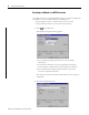
Address I/O Data
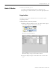
I/O information is presented as a set of tags.
• Each tag uses a structure of data. The structure depends on the specific
features of the I/O module.
• The name of the tags is based on the location of the I/O module in the
system.
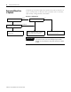
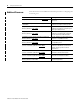
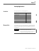
An I/O address follows this format.
Location :Slot :Type .Member .SubMember .Bit
= Optional
I/O Address Components
Where Is
Location Network location
LOCAL = same chassis or DIN rail as the controller
ADAPTER_NAME = identifies remote communication adapter or bridge module
Slot Slot number of I/O module in its chassis or DIN rail
Type Type of data
I = input
O = output
C = configuration
S = status
Member Specific data from the I/O module, depending on what type of data the module can store
• For a digital module, a data member usually stores the input or output bit values
• For an analog module, a channel member (CH#) usually stores the data for a channel
Submember Specific data related to a member
Bit Specific point on a digital I/O module; depends on the size of the I/O module (0...31 for a 32-point module)