
User manual


51 Publication 1768-UM001C-EN-P - November 2007
Chapter
5
Place 1768 and 1769 Modules
Introduction
This chapter explains the placement of 1768 and 1769 modules.
The 1768 CompactLogix controllers combine a 1768 backplane with a 1769
backplane. This combination includes the advantages of the 1768 architecture
while retaining the advantages of 1769 I/O support.
1768 Module Placement
Follow these guidelines as you place modules in the 1768 backplane.
1768 Module Placement Overview
Topic Page
1768 Module Placement 51
1769 Module Placement 53
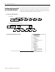
1768 CompactLogix Controller Guidelines
1768-L43 and
1768-L45
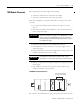
The 1768 power supply must be the leftmost module in the 1768 backplane.
The controller must be the rightmost module in the 1768 backplane.
Up to two 1768 communication modules can reside between the controller and power supply in
any one of these combinations:
• 1768-ENBT or 1768-EWEB for EtherNet/IP communication (maximum of two)
• 1768-CNB or 1768-CNBR for ControlNet communication (maximum of two)
1768-L43 Two chassis slots are available.
The controller supports a maximum of 3 banks for a total of 16 modules.
1768-L45 Four chassis slots are available.
The controller supports a maximum of 3 banks for a maximum of 30 modules.
Up to four 1768-M04SE for SERCOS motion control modules can be used.
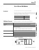
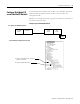
Place 1768 modules in the 1768 backplane.
1768 Modules1768
Power
Supply
Slot 0Slot 1Slot 2
1768-L43 controller is shown.