
User manual


Publication CIG-WD001A-EN-P - October 2003
7-12 1762 I/O on MicroLogix 1200 Controllers
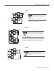
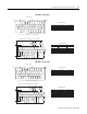
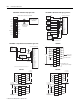
V out 3
V out 2
V out 1
V out 0
I out 3
I out 2
I out 1
I out 0
COM
COM
Current Load
Voltage Load
Analog outputs may fluctuate for less than a second when power is applied or
removed. This characteristic is common to most analog outputs. While the majority of
loads will not recognize this short signal, it is recommended that preventive measures
be taken to ensure that connected equipment is not affected.
TIP
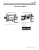
Grounding the cable shield at the module end only usually provides sufficient noise
immunity. However, for best cable shield performance, earth ground the shield at both
ends, using a 0.01 µF capacitor at one end to block AC power ground currents,
if necessary.
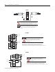
1762-OF4
OUT 2
OUT 0
OUT 3
OUT 1
VAC-VDC
0
CR
CR
CR
OUT 6
OUT 4
OUT 7
OUT 5
CR
CR
CR
OUT 10
OUT 8
OUT 11
OUT 9
VAC-VDC
1
CR
CR
CR
OUT 14
OUT 12
OUT 15
OUT 13
CR
CR
CR
L1 or +DC
L2 or -DC
L1 or +DC
L2 or -DC
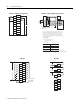
Be careful when stripping wires. Wire fragments that fall into a
module could cause damage when power is applied.
Once wiring is complete, ensure the module is free of all
metal fragments.
Surge Suppression – Connecting surge suppressors across your external inductive
load will extend the life of the relay contacts. For additional details, refer to
Industrial Automation Wiring and Grounding Guidelines, Allen-Bradley publication 1770-4.1.
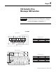
1762-OW16
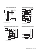
OUT 5
VA C-VDC
1
OUT 2
OUT 0
OUT 7
OUT 4
OUT 3
OUT 1
VA C-VDC
0
OUT 6
CR
CR
CR
CR
CR
CR
L1 or +D C
L2 or -DC
L1 or +D C
L2 or -DC
Be careful when stripping wires. Wire fragments that fall into a
module could cause damage when power is applied.
Once wiring is complete, ensure the module is free of all
metal fragments.
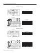
Surge Suppression – Connecting surge suppressors across your external inductive
load will extend the life of the relay contacts. For additional details, refer to
Industrial Automation Wiring and Grounding Guidelines, Allen-Bradley publication 1770-4.1.
1762-OW8