www.jdna.
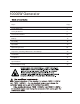
10000W Generator Topi c Page Limited Warrant y 3 S a fet y G u i d e l i n e s 5 G e n e r a l Pr e c a u t i o n s 6 Battery 15 Assembly 16 Operation 17 Spark Plug Service 22 Inspection, Cleaning, Maintenance and Storage 23 Installation 29 Compliance 31 Speci fications 32 General Par ts Listing 33
10000W Generator
Owner’s Manual Safety Guidelines - Definitions This manual contains important information that you need to know and understand in order to protect YOUR SAFETY and to PREVENT EQUIPMENT PROBLEMS. The following symbols help you recognize this information. Please read the manual and pay attention to these sections. Save These Important Safety Instructions! Read and understand all of these safety instructions. Be sure to retain them for future use.
10000W Generator General Precautions WARNING! FAILURE TO FOLLOW THESE INSTRUCTIONS CAN RESULT IN SEVERE INJURY OR DEATH. CAUTION: FAILURE TO FOLLOW THESE INSTRUCTIONS CAN ALSO RESULT IN DAMAGE TO THE TOOL AND/OR THE ITEM YOU ARE WORKING ON. DANGER CARBON MONOXIDE Using a generator indoors WILL KILL YOU IN MINUTES. Generator exhaust contains high levels of carbon monoxide (CO), a poisonous gas you cannot see or smell. If you can smell the generator exhaust, you are breathing CO.
Owner’s Manual • Fuel or oil spills must be cleaned up immediately. Dispose of fluids and cleaning materials as per any local, state, or federal codes and regulations. Store oily rags in a covered metal container. • Never store fuel or other flammable materials near the generator. General Precautions (cont’d) Gasoline and Oil (cont’d) • Do not smoke, or allow sparks, flames or other sources of ignition around the engine and fuel tank. Fuel vapors are explosive.
10000W Generator General Precautions (cont’d) Work Area • Keep your work area clean and well lit. Cluttered benches and dark areas invite accidents. • Do not operate power tools in explosive atmospheres, such as in the presence of flammable liquids, gases, or dust. Generators create sparks which may ignite the dust or fumes. • Keep bystanders, children, and visitors away while operating a generator. Provide barriers or shields as needed.
Owner’s Manual General Precautions (cont’d) Electrical Safety (cont’d) • All connections and conduits from the generator to the load must only be installed by trained and licensed electricians, and in compliance with all relevant local, state, and federal electrical codes and standards, and other regulations where applicable. • The generator must be earth-grounded for fixed installations in accordance with all relevant electrical codes and standards before operation.
000W Generator General Precautions (cont’d) Personal Safety (cont’d) • Avoid accidental starting. Make sure the power switch is in its “OFF” position, and disconnect the spark plug wire when not in use. • Remove adjusting keys or wrenches before turning the generator on. A wrench or a key that is left attached to a rotating part of the generator may result in personal injury. • Do not overreach. Keep proper footing and balance at all times. • Use safety equipment. Always wear eye protection.
Owner’s Manual General Precautions (cont’d) Servicing Maintain labels and name plates on the generator and engine. These carry important information. If unreadable or missing, contact our service center toll free at 888-896-6881 immediately for a replacement. Generator service must be performed only qualified repair personnel. Service or maintenance performed by unqualified personnel could result in a risk of injury. When servicing a generator, use only identical replacement parts.
10000W Generator General Precautions (cont’d) Installation (cont’d) • If the generator is installed outdoors, it must be weatherproofed and should be soundproofed. It should not be run outdoors without protection to the generator and wiring conduit. • The generator weighs 100 lbs (approx). Two or more people should assist when moving or lifting this product. Never lift the generator using the engine or alternator lifting lugs.
Owner’s Manual General Precautions (cont’d) Mechanical (cont’d) • Do not operate the generator with safety guards removed. While the generator is running, do not attempt to reach around the safety guard for maintenance or any other reason. • Keep hands, arms, long hair, loose clothing, and jewelry away from moving parts. Be aware that when engine parts are moving fast they cannot be seen clearly. • Keep access doors on enclosures closed and locked when access is not required.
10000W Generator General Precautions (cont’d) Extension Cord If an extension cord (not included) is used, make sure to use only UL approved cords having the correct gauge and length according to the following table: Nameplate Amps (@ full load) Cord Lengths 0 ft.- 50 ft. 50 ft.-100 ft. 100 ft.-150 ft. 150 ft.-200 ft. 0-5 5.1 - 8 16 AWG 16 AWG 16 AWG 14 AWG 12 AWG 10 AWG 12 AWG - 8.1 - 12 12.
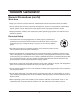
Owner’s Manual Battery To start generator with electric start you will need a battery (not included). You can use a 12v lawn tractor battery with the following specifications: The dimensions are Wx7.5” Dx5” Hx7” (including terminals). A rated cranking amperage of 200. Terminals are regular, not reversed. Note: Using a battery not designed for this unit may void warranty. Also this generator can also be started with the pull start. Photos below demonstrate battery plate attachment.
10000W Generator Assembly Unpacking 1. Remove the generator and loose parts box from the carton. 2. Compare the accessory with the inventory list below. Loose Parts (Wheel kit and handle) Check all loose parts against the following list. Contact your dealer toll free at 888.896.
Owner’s Manual Operation Control Panel Choke lever Handle Battery Oil plug Air filter Recoil Start NOTE: THE PARTS LISTED ABOVE ARE HELPFUL FOR LOCATING THE CONTROLS MENTIONED BELOW. CAUTION: PRIOR TO FIRST USING THE GENERATOR, THE ENGINE MUST BE FILLED WITH OIL OF A HIGH QUALITY SAE 10W-30 GRADE ENGINE OIL. TO DO SO, UNSCREW AND REMOVE THE ENGINE’S OIL DIPSTICK LOCATED AT THE BOTTOM OF THE ENGINE CRANKCASE.
10000W Generator Operation (cont’d) Starting 1. Put the engine switch on the “RUN” positi on. The engine switch enables and disables the ignition system. STOP: To stop the engine RUN: To run the engine START: To Start the engine 2. The fuel valve is located under the fuel tank . When the valve lever is in the ON positio n, fuel is allowed to flow from the fuel tank to th e carburetor. Be sure to return the fuel valve lever to the “ OFF” position after stopp ing the engine. 2) ) 21 3.
Owner’s Manual Operatio n (cont’d) Starting 4. Operate the Recoil Start: Pull the starter grip lightly until you feel resistance, then pull briskly. Return the starter grip gently. Pulling the starter grip operates the recoil start to crank the engine Operate the Electric start: Push and hold the engine switch on the “START” position for 3~5s and crank the engine. 6 WDUWHU *ULS 5.
10000W Generator Operation (cont’d) Powering 120 Volt AC Tools And Equipment: 1. Prior to powering tools and equipment, make sure the generator’s rated voltage, and amperage capacity (120 V AC @ 66.7 AMPs) is adequate to supply all electrical loads that the unit will power. If powering exceeds the generator’s capacity, it may be necessary to group one or more of the tools and/or equipment for connection to a separate generator.
Owner’s Manual Operation (cont’d) Powering 12 Volt DC tools and Equipment: 1. Prior to powering tools and equipment, make sure the generator’s rated voltage, and amperage capacity (12V DC) is adequate to supply all electrical loads that the unit will power. If powering exceeds the generator’s capacity, it may be necessary to group one or more of the tools and/or equipment for connection to a separate generator. 2. Connect the power cord of a 12 VDC powered tool or equipment to the DC Terminals.
10000W Generator Spark Plug Service In order to service the spark plug, you will need a spark plug wrench (commercially available). Recommended spark plugs: NHSP LD F7TC or NGKBPRGES but we recommend our OEM spark plug. To ensure proper engine operation, the spark plug must be properly gapped and free of deposits. 1. Remove the spark plug cap. 2. Clean any dirt from around the spark plug base. 3. Use a spark plug wrench to remove the spark plug. 4. Visually inspect the spark plug.
Owner’s Manual Inspection, Cleaning, and Maintenance WARNING! ALWAYS MAKE SURE THE ENGINE POWER SWITCH (2) IS IN ITS “OFF” POSITION. DISCONNECT THE SPARK PLUG WIRE FROM THE ENGINE. AND ALLOW SUFFICIENT TIME FOR THE ENGINE AND GENERATOR TO COMPLETELY COOL BEFORE PERFORMING ANY INSPECTIONS, MAINTENANCE, OR CLEANING.
10000W Generator Fuel Sediment Cup Cleaning The sediment cup prevents dirt or water which may be in the fuel tank from entering the carburetor. If the engine has not been run for a long time, the sediment cup should be cleaned. 1. Turn the fuel valve to the OFF position. Remove the sedement cup, and O-ring. 2. Clean the sediment cup, and O-ring, in nonflammable or high flash point solvent. 3. Reinstall O-ring, and sediment cup. 4. Turn the fuel valve ON and check for leaks.
Owner’s Manual Maintenance Guide Periodic maintenance and adjustment is necessary to keep the generator in good operating condition. WARNING! Exhaust gas contains poisonous carbon monoxide. Shut off the engine before performing any maintenance. If the engine must be run, make sure the areas is well ventilated. • Before each use, inspect the generator.
10000W Generator Air cleaner service A dirty air cleaner will restrict air flow to the carburetor. To prevent carburetor malfuncion, service the air cleaner regularly. Service more frequently when operating the generator in extremely dusty areas. WARNING! Using gasoline or flammable solvent to clean the filter element can cause a fire or explosion. Use only soapy water or nonflammable solvent. NOTE: Never run the generator without the air cleaner. Rapid engine wear will result. 1.
Owner’s Manual 27
10000W Generator Transporting/Storage 28
Owner’s Manual Installation NOTE: PRIOR TO POWERING TOOLS AND EQUIPMENT MAKE SURE THE GENERATOR’S RATED VOLTAGE, WATTAGE AND AMPERAGE CAPACITY IS ADEQUATE TO SUPPLY ALL ELECTRICAL LOADS THAT THE UNIT WILL POWER. IF POWERING EXCEEDS THE GENERATOR’S CAPACITY, IT MAY BE NECESSARY TO GROUP ONE OR MORE OF THE TOOLS AND/OR EQUIPMENT FOR CONNECTION TO A SEPARATE GENERATOR. Electrical and other permits may be required for the installation of emergency power systems.
10000W Generator Installation (cont’d) Supporting and Mounting Mount the generator on a concrete slab capable of supporting the weight of the generator. The slab must extend on all sides beyond the frame by at least one foot. Contact a cement contractor for slab specifications if necessary. Attach the frame to the concrete slab using 3/8” diameter expansion anchor bolts (not supplied).
120V/240 AC @ 66.7/33.3A 60Hz :$776 :$776 (1) 120/240V AC twist-lock outlet EPA approved 77 11 hours(approx.) @ 1/2 load 220 lbs.
PARTS LISTING 33
10000 W Generator Cylinder head system assy. APA Part No. Description JD Pa= rt No. = Qty APGG10000-A-01-JD JF240.1.1-4 HEAD COVER COMP. BOLT 1 APGG10000-A-02-JD JF240.1.1-6 HEAD COVER WASHER COMP 1 APGG10000-A-03-JD JF240.1.1-5 WASHER COVER PACKING 1 APGG10000-A-04-JD JF240.1.3-1 HEAD COVER COMP 1 APGG10000-A-05-JD JF240.1.1-3 HEAD COVER PACKING 1 APGG10000-A-06-JD JF340.2-4 FLANGE BOLT (M10X80) 4 APGG10000-A-07-JD JF168.10-1 SPARK PLUG 1 APGG10000-A-08-JD JF240.
10000W Generator Cylinder barrel Description Qty APA Part No. JD Part No. APGG10000-B-01-JD 20.4-M6*16 HEX HEAD FLANGE BOLT (M6X 16) 2 APGG10000-B-02-JD JF340.14.1 OIL LEVEL SWITCH ASSY 1 APGG10000-B-03-JD 20.6-M10 FLANGE NUT (M10) 1 APGG10000-B-04-JD 20.4-M6*12 HEX HEAD FLANGE BOLT (M6X 12) 1 APGG10000-B-05-JD JF420.2.1-1 CRANK CASE 1 APGG10000-B-06-JD 20.2-6207 BALL BEARING (6207) 1 APGG10000-B-07-JD JF168.11.2-8 WASHER( ø8.3×ø17×1) 1 APGG10000-B-08-JD JF168.11.
10000W Generator Crankcase cover system assy. C JD Part No. Description Qty APGG10000-C-01-JD JF340.17.3 DUCT COVER 1 APGG10000-C-02-JD 20.4-M8*35 FLANGE BOLT (M8 X 35) 1 APGG10000-C-03-JD JF240.15-3B OIL SCALE 1 APGG10000-C-04-JD JF340.15-5 OIL SCALE SEAL RING 1 APGG10000-C-05-JD 20.1-35*52*7 OIL SEAL 1 APGG10000-C-06-JD JF340.15-2 FLANGE BOLT (M8X35) 6 APGG10000-C-07-JD JF340.15-1B CRANKCASE COVER 1 APGG10000-C-08-JD JF340.11.
10000W Generator Crankshaft system assy. 2 D Descript io n Qty A PA Par t No . JD Part No. APGG10000-D-01-JD JF420.4.2 CRANKSHAFT COMP.(Tapper shaft) 1 APGG10000-D-02-JD JF340.
10000W Generator Piston & Connecting Rod Assy. A PA Par t No . JD Pa= rt No. = Descript io n Qty APGG10000-E-01-JD JF420.3-1C COMPRESSION RING A 1 APGG10000-E-02-JD JF420.3-2C COMPRESSION RING B 1 APGG10000-E-03-JD JF420.3-3C-1 OIL RING A 1 APGG10000-E-04-JD JF420.3-3C-2 OIL RING B 1 APGG10000-E-05-JD JF340.3-6 PISTON PIN CLIP (20 mm) 1 APGG10000-E-06-JD JF420.3-5C PISTON 1 APGG10000-E-07-JD JF390.3-4 PISTON PIN 1 APGG10000-E-08-JD JF420.3.
10000W Generator Valve Train Assembly A PA Par t N o . JD Part No. Descript io n Qty APGG10000-F-01-JD JF168.1.2-17 PIVOT ADJUSTING NUT 2 APGG10000-F-02-JD JF340.1.2-8 ROCKER ARM PIVOT 2 APGG10000-F-03-JD JF340.1.2-9 ROCKER ARM 2 APGG10000-F-04-JD JF340.1.2-7 PIVOT BOLT (M8) 2 APGG10000-F-05-JD JF340.1.2-16 PUSH ROD GUIDE PLATE 2 APGG10000-F-06-JD JF340.1.2-14 ROD PUSH 2 APGG10000-F-07-JD JF340.1.2-15 VALVE LIFTER 2 APGG10000-F-08-JD JF340.
10000W Generator Recoil Starter Assy. 1 Qty A PA Par t N o . JD Pa= rt No. = APGG10000-G-01-JD JF340.13.1 RECOIL STARTER ASSY. 1 APGG10000-G-02-JD JF340.13.1-7 SETTING SCREW 1 APGG10000-G-03-JD JF340.13.1-6 SPRING RETAINER 1 APGG10000-G-04-JD JF340.13.1-8 PLATEN SPRING 2 APGG10000-G-05-JD JF340.13.1-5 STARTER DETENT 2 APGG10000-G-06-JD JF340.13.1-4 DETENT SPRING 2 APGG10000-G-07-JD JF340.13.1-3 RECOIL STARTER REEL 1 APGG10000-G-08-JD JF340.13.
10000W Generator Fan Cover Assy. H Qty A PA Par t N o . JD Part No. Descript io n APGG10000-H-01-JD JF420.12-1 SHROUD APGG10000-H-02-JD 20.4-M6*12 FLANGE BOLT (M6 X 12) 4 APGG10000-H-03-JD JF340.13.2 FAN COVER COMP.
10000W Generator Carburetor Assy. 1 2 3 APA Part No. JD Pa= rt No. = 4 I Description Qty APG10000-I-01-JD JF420.9.1D CARBURETOR ASSY. 1 APG10000-I-02-JD JF340.9-3 CARBURETOR PAPER GASKET 1 APG10000-I-03-JD JF340.9-1A CARBURETOR INSULATING PLATE 1 APG10000-I-04-JD JF340.
10000W Generator Flywheel Assy. 5 2 4 3 J A PA Par t No . JD Part No. Descript io n Qty APGG10000-J-01-JD JF420.4.1 FLYWHEEL 1 APGG10000-J-02-JD JF168.4.2-2 SPECIAL WOODRUFF KEY 1 APGG10000-J-03-JD JF340.12-1 COOLING FAN 1 APGG10000-J-04-JD JF340.13-1 STARTER PULLEY 1 APGG10000-J-05-JD JF240.
10000W Generator Ignition System Assy. Qty A PA Par t N o . JD Pa= rt No. = APGG10000-K-01-JD JF340.10.2-1 NOISE SUPPERSSOR CAP ASSY 1 APGG10000-K-02-JD JF340.10.2-2 IGNITION COIL ASSY 1 APGG10000-K-03-JD JF340.10.2-3 STOP SWITCH CORD 1 APGG10000-K-04-JD JF340.10-3 STOP SWITCH CORD HOLDER 1 APGG10000-K-05-JD 20.4-M6*25 FLANGE BOLT (M6 X 25) 1 APGG10000-K-06-JD JF340.
10000W Generator Starter Motor Assy. Qty APA Part No. JD Part No. Descript io n APGG10000-L-01-JD JF340.18-1 STARTER MOTOR 1 APGG10000-L-02JD JF340.18-2 SOLENOID 1 APGG10000-L-03-JD 20.
10000W Generator Control Assy. Qty A PA Par t No . JD Part No. APGG10000-M-01-JD JF340.11.4 CONTROL ASSY. 1 APGG10000-M-02-JD JF340.11.4-1 CONTROL BASE COMP. 1 APGG10000-M-03-JD JF340.11.4-3 CONTROL ADJUSTING SPRING 1 APGG10000-M-04-JD JF340.11.4-4 PAN SCREW (M5 X 34) 1 APGG10000-M-05-JD 20.4-M6*12 FLANGE BOLT (M6 X 12) APGG10000-M-06-JD JF340.11.2-5A THROTTLE RETURN SPRING APGG10000-M-07-JD JF340.11.2-6 GOVERNOR SPRING 1 APGG10000-M-08-JD JF340.11.
10000W Generator Muffler Assy. 3 4 N Part No. APA Part No. Descript io n APG10000-N -01-JD 20.4-M8*16 FLANGE BOLT (M8 X 16) 4 APG10000-N -02-JD 20.4-M6*12 FLANGE BOLT (M6 X 12) 4 APG10000-N -03-JD JD6500.17.10.1.5-1 MUFFLER STAY COMP. 1 APG10000-N -04-JD JD6500.17.10.1.5-2 MUFFLER PROTECTOR SEAL 1 APG10000-N -05-JD JD6500.17.10.1.5-3 MUFFLER SIDE PROTECTOR 1 APG10000-N -06-JD JF340.7.2-3 MUFF. INNER PROTECTOR COM 1 APG10000-N -07-JD JF340.7.
10000W Generator Air Cleaner Description O APA Part No. JD Part No. APGG10000 -O-01-JD JF240.6.2-1 AIR CLEANER COVER COMP 1 APGG10000 -O-02-JD JF240.6.2-2 AIR CLEANER ELEMENT 1 APGG10000 -O-03-JD 20.6-M5 FLANGE NUT (M5) 6 APGG10000 -O-04-JD JF240.6.2-4 AIR CLEANER SEPARATOR 1 APGG10000 -O-05-JD JF240.6.2-3 AIR CLEANER SEAL 1 APGG10000 -O-06-JD JF240.6.2-5 AIR CLEANER CASE COMP 1 APGG10000 -O-07-JD JF240.6.
10000W Generator Fuel Tank Assy. 1 2 7 8 P 5 6 4 3 6 APA Part No. JD Part No Descript io n APGG10000 -P-01-JD JD6500W-U.1.5-1.2 FUEL FILTER CAP COMP APGG10000 -P-02-JD JD6500W-U.1.5-1.1 FUEL FILTER 1 APGG10000 -P-03-JD JD10000W-U.1.5-1C FUEL TANK COMP. 1 Qty 1 APGG10000 -P-04-JD JF168.8-1A FUEL TUBED 1 APGG10000 -P-05-JD JF168.8-5 FUEL VALVE 1 APGG10000 -P-06-JD JF168.8-3 TUBECLIP C 2 APGG10000 -P-07-JD 20.4-M6*25 FLANGE BOLT (M6x25) 4 APGG10000 -P-08-JD JF168.8.2.
10000W Generator Control Box Assy. 4 10 1 2 13 14 3 11 6 12 5 5 7 8 9 Description Q APA Part No. JD Part No. APGG10000 -Q-01-JD HC001-MB CONTROL PANEL COMP. 1 APGG10000 -Q-02-JD 21.3.1-13 ENGINE SWITCH ASSY. 1 APGG10000 -Q-03-JD 21.3.4-15 DC 12V OUTPUT 1 APGG10000 -Q-04-JD 21.3.16-2 HOURS METER 1 APGG10000 -Q-05-JD 21.3.4-5 120V RECEPTACLE(Ru-22) 1 APGG10000 -Q-06-JD 21.3.7-7 CIRCUIT BREAKER (SINGLE, 20A) 1 APGG10000 -Q-07-JD 21.3.
10000W Generator Frame Comp Assy. 2 1 APA Part No. Description JD Part No. Qty APGG10000-R-01-JD JD6500.17.10.1-J109 GENERATOR FRAME 1 APGG10000-R-02-JD 21.3.25-11 .
10000W Generator Generator 7 11 APA Part N o. JD Part No Description Qty. APGG10000 -S-01-JD 7KW.25.3A STATOR COVER 1 APGG10000 -S-02-JD 7.5KW.25.02B STATORASSY 1 APGG10000 -S-03-JD 5KW.25.2-8A COOLING FAN 1 APGG10000 -S-04-JD 5KW.25.4A BRUSH ASSY 1 APGG10000 -S-05-JD 20.4-M5*16*0.75 TAPPING SCREW 3 RR HOUSING 1 APGG10000 -S-06-JD JF240.22-1 APGG10000 -S-07-JD 20.9-M5 SPRING WASHER (5mm) 4 APGG10000 -S-08-JD 20.
10000W Generator Generator APA Part No. JD Part No. APGG10000-S-18-JD 20.4-M5*16*0.75 APGG10000-S-19-JD APGG10000-S-20-JD Description Qty HEX.BOLT (M5 X 20) 2 2KW.25.5-1 VOLT CHANGE TERMINAL BR-AC-W 1 20.
10000W Generator Wheel & Hand Assy. 3 7 7 7 14 14 1 2 16 15 6 12 4 12 15 16 9 11 9 9 9 4 6 6 14 14 2 1 13 10 11 8 3 6 5 13 7 8 T APA Part No JD Part No Description Qty. APGG10000 -T-01-JD JD6500.17.10.1-1 PIN SPLIT 2 APGG10000 -T-02-JD JD6500.17.10.1-2 WSHER PLAIN 2 APGG10000 -T-03-JD 8 inch wheel WHEEL 2 2 APGG10000 -T-04-JD JD6500.17.10.1-J109.1-1 BAFFLE APGG10000 -T-05-JD JD6500.17.10.1-J109.1 SHAFT 1 APGG10000 -T-06-JD 20.