
User`s guide

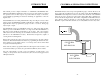


CABLING TO THE DIO CONNECTOR
The CIO-DIO48 connector is accessible through the PC/AT expansion bracket. The
connector is a standard 50 pin male header connector. A mating female connector
may be purchased at Radio Shack or other electronic supply outlets.
SIGNAL CONNECTION - CIO-DIO48
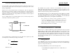
All the digital outputs and inputs on the CIO-DIO48 connector are CMOS/TTL. TTL
is an electronics industry term, short for Transistor-Transistor Logic, which describes
a standard for digital signals which are either at 0V or 5V.
Under normal operating conditions, the voltages on the 82C55 pins range from 0 to
0.45 volts for the low state to between 2.4 to 5.0 volts for the high state. At a voltage
of 0.45 volts the 82C55 can safely sink 2.5 mA. At a voltage of 2.4 volts the 82C55
can source 2.5 mA.
The voltages and currents associated with external devices range from less than a hun-
dred mA at a few volts for a small flash light bulb to 50 Amps at 220 volts for a large
electric range. Attempting to connect either of these devices directly to the CIO-DIO
would destroy the I/O chip.
In addition to voltage and load matching, digital signal sources often need to be de-
bounced. A complete discussion of digital interfacing will be found in the section on
Interface Electronics in this manual.
IMPORTANT NOTE
The 82C55 digital I/O chip initializes all ports as inputs on power
up and reset. A TTL input is a high impedance input. If you con-
nect another TTL input device to the 82C55 it will probably be
turned ON every time the 82C55 is reset, or, it might be turned
OFF instead. Remember, and 82C55 which is reset is in INPUT
mode.
To safeguard against unwanted signal levels, all devices being controlled by an 82C55
should be tied low (or high, as required) by a resistor.
You will find positions for pull up and pull down resistor packs on your CIO-DIO
board. To implement these, please turn to the application note on pull up/down resis-
tors.
7
ELECTRONICS AND INTERFACING
This short, simple introduction to the electronics most often needed by digital I/O
board users covers a few key concepts. They are:
Pull up/down resistors
Transistors.
Power MOSFETs
Solid State Relays
Voltage dividers.
Low pass filters for digital inputs.
Noise; sources and solutions.
IMPORTANT NOTE
It cannot be stated often enough to those unfamiliar with the
82C55. WHENEVER THE 82C55 IS POWERED ON OR RESET,
ALL PINS ARE SET TO HIGH IMPEDANCE INPUT.
The implication of this fact is that if you have output devices such as solid state relays,
they may be switched on whenever the computer is powered on or reset. To prevent
unwanted switching and to drive all outputs to a known state after power on or reset,
pull all pins either high or low through a 2.2K ohm resistor.
To install pull up/down resistor packs, see the application note.
PULL UP & PULL DOWN RESISTORS
This discussion deals with pull up/down resistors and 82C55 digital I/O chips on CIO-
DIO boards.
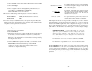
Whenever the 82C55 is powered on or reset, the control register is set to a known
state. That state is mode 0, all ports input.
When used as and output device to control other TTL input devices, the 82C55
applies a voltage level of 0V for low and 2.5V-5V for high. It is the output voltage
level of the 82C55 that the device being controlled responds to.
16