
User`s guide


82C55 DIGITAL I/O REGISTERS
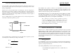
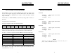
PORT A DATA
BASE ADDRESS +0
A0A1A2A3A4A5A6A7
01234567
PORT B DATA
BASE ADDRESS +1
B0B1B2B3B4B5B6B7
01234567
Ports A & B may be programmed as input or output. Each is written to and read from
in Bytes, although for control and monitoring purposes the individual bits are more
interesting.
Bit set/reset and bit read functions require that unwanted bits be masked out of reads
and ORed into writes.
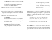
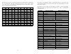
PORT C DATA
BASE ADDRESS +2 (8-bit mode)
CL1CL2CL3CL4CH1CH2CH3CH4
C1C2C3C4C5C6C7C8
01234567
Port C may be used as one 8 bit port of either input or output, or it may be split into
two 4 bit ports which may be independently input or output.
PORT C DATA
BASE ADDRESS +2 (4-bit mode)
CL1CL2CL3CL4CH1CH2CH3CH4
C1C2C3C4C5C6C7C8
01234567
The notation for the upper 4 bit port is PCH3-PCH0, and for the lower, PCL3-PCL0.
Although it may be split, every read and write to port C carries 8 bits of data so
unwanted information must be ANDed out of reads, and writes must be ORed with the
current status of the other port.
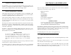
OUTPUT PORTS
11
In 82C55 mode 0 configuration, ports configured for output hold the output data writ-
ten. The output byte may be read back by reading a port configured for output.
INPUT PORTS
In 82C55 mode 0 configuration, ports configured for input read the state of the input
lines at the moment the read is executed, transitions are not latched.
For information on modes 1 (strobed I/O) and 2 (bi-directional strobed I/O), you will
need to acquire an Intel or AMD data book and see the 82C55 data sheet.
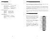
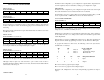
82C55 CONTROL REGISTER
BASE ADDRESS +3
Group BGroup A
CLB M1CUAM2M3MS
01234567
The 82C55 may be programmed to operate in Input/ Output (mode 0), Strobed Input/
Output (mode 1) or Bi-Directional Bus (mode 2).
Included here is information on programming the 82C55 in mode 0. Those wishing to
use the 82C55 in modes 1 or 2, must procure a data book from Intel Corporation Lit-
erature Department.
When the PC is powered up or RESET, the 82C55 is reset. This places all 24 lines in
Input mode and no further programming is needed to use the 24 lines as TTL inputs.
To program the 82C55 for other modes, the following control code byte must be
assembled into on 8 bit byte.
Bi-DirectionalMode 2X1
Strobed Input / OutputMode 110
Input / OutputMode 000
Group A FunctionM2M3
Output0000
Input1111
Independent FunctionCHCLBA
M1 = 0 is mode 0 for group B. Input / Output
M1 = 1 is mode 1 for group B. Strobed Input / Output
The Ports A, B, C High and C Low may be independently programmed for input or
output.
12