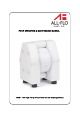
PUMP OPERATION & MAINTENANCE MANUAL T025 – T200 High Purity Air Operated Double Diaphragm Pump
TABLE OF CONTENTS 1. Warnings and Cautions ______________________________________________________________ 3 2. Pump Model Matrix _________________________________________________________________ 4 3. Pump Dimensions and Specifications ___________________________________________________ 5 4.
I All-Flo Pump Co.
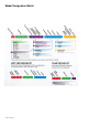
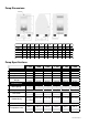
Model Designation Matrix 4 I All-Flo Pump Co.
Pump Dimensions A B C D E F G H I ØJ K L T025 2.76” 4.5” 4.72” .59” G 1/4" 2.28” R 1/8" 4.23” .40” .60” 1.97” 3.39” T038 4.13” 5.04” 6.66” .71” G 3/8" 3.31” R 1/8" 5.91” .40” .60” 2.95” 3.66” T050 6.02” 6.97” 9.25” .98” G 1/2" 3.43” R 1/4" 8.54” .71” 118” 4.41” 5.35” T100 7.78” 9.13” 12.28” 1.38” G 1" 4.84” R 1/4" 11.30” 110” 1.58” 551” 6.70” T150 10.63” 12.28” 16.77” 1.65” G 1 1/2" 4.29” R 1/2" 15.28” 1.18” 2.36” 7.48” 8.94” T200 13.
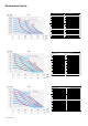
Performance Curves T025 Performance Specifications Max. Flow: 2.6 gpm (10 lpm) Max. Air Pressure: 116 PSI (8 bar) Max. Solids: 1/16" (2 mm) Max. Suction Lift Dry: 1.6 ft-H2O (0.5 m-H2O) Max. Suction Lift Wet: 29.5 ft-H2O (9 m-H2O) Weight: 3.3 lbs (1.5 kg) Air Inlet: 1/8" Liquid Inlet: 1/4" Liquid Outlet: 1/4" Height 5.12" (130 mm) Width: 4.5" (114 mm) Depth: 2.76" (70 mm) T038 Performance Specifications Max. Flow: 6.6 gpm (25 lpm) Max. Air Pressure: 116 PSI (8 bar) Max. Solids: 1/8" (3 mm) Max.
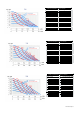
T100 Performance Specifications 33 gpm (125 lpm) Max. Flow: Max. Air Pressure: 116 PSI (8 bar) Max. Solids: 9/32" (7 mm) Max. Suction Lift Dry: 13.1 ft-H2O (4 m-H2O) Max. Suction Lift Wet: 29.5 ft-H2O (9 m-H2O) Weight: 36.4 lbs (16.5 kg) Air Inlet: 1/4" Liquid Inlet: 1" Liquid Outlet: 1" Height 13.38" (340 mm) Width: 19.13" (232 mm) Depth: 7.78" (198 mm) T150 Performance Specifications 83 gpm (315 lpm) Max. Flow: 116 PSI (8 bar) Max. Air Pressure: 3/8" (10 mm) Max. Solids: Max. Suction Lift Dry: 13.
Installation, Troubleshooting and Maintenance Installation Piping Whenever possible ensure the pump is installed using the shortest possible pipe lengths with the minimum amount of pipe fittings. Ensure all piping is supported independent of the pump. Suction and discharge piping should not be smaller than the connection size of the pump. When pumping liquids of high viscosity, larger piping may be used, in order to reduce frictional pipe loss.
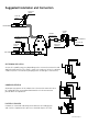
Suggested Installation and Connection pressure gauge shut-off valve DISCHARGE flexible connection flexible connection needle valve vacuum gauge shut-off valve AIR SUPPLY combined air filter and regulator air shut-off valve SUCTION SELF PRIMING APPLICATION Suction lift capability may vary depending on the construction materials and application parameters. The range is from 16.4 feet dry to 30 feet in a primed condition (values calculated for pumping water at 68 degrees Fahrenheit).
Troubleshooting PROBLEM Pump Will Not Cycle Pumped Fluid Coming Out of Muffler Pump Cycles but no Flow Pump Cycles with Closed Discharge Valve Pump Running Slowly/Not Steady Pump Will Not Prime EFFECT/SOLUTION Discharge line closed or plugged Discharge filter blocked Check valve stuck Air filter blocked Air supply valve closed Air supply hooked up to muffler side of pump Compressor not producing air or turned off Muffler iced or blinded Diaphragm ruptured Plant air supply line ruptured Air valve wear/
Operation ! ! ! ! CAUTION Before starting the pump, check that all piping is properly connected. Before starting the pump, check that all the bolts are securely tightened. Check that the regulator and the drain valve on the discharge side are closed and that the valve on the suction side is opened if applicable. 1) Start the air compressor. 2) Open the air valve. Using a regulator to adjust the supply air pressure within the permissible range. 3) Open the flow valve on the discharge side.
Maintenance Cleaning the Pump ! ! ! WARNING Make sure that compressed air is not supplied to the pump BEFORE you start cleaning the pump. Make sure that the pump is not pressurized BEFORE you start cleaning the pump. 1) Remove the hose from the suction side of the pump. 2) Close the flow valve on the discharge side and open the drain valve. Then start air pressure for a while to discharge possibly much fluid remaining inside the pump.
Shutdown Close the air valve of the pump and shut off the supply air. ! ! ! The pump can be shut down with the flow valve closed while air is being supplied. However DO NOT leave the pump in this condition for many hours without supervision - there is a risk of a leak from the pump or piping, and fluid may continue flowing out of the position of leakage. When the pump is shut down while pumping slurry, particulate matter contained in the slurry will be deposited and get stuck inside the out chamber.
Exploded View & Parts List T025, T038 5 22 12 Sleeve with Split connections – T038 only 18 1 11 24 7 2 9 25 15 28 17 14 13 4 70 7 3 98 97 27 26 99 14 I All-Flo Pump Co.
Parts List for T025 and T038 pumps T025 T038 1 2 Pump housing PTFE HP-2 08 01 23 HP-2 10 01 23 2 1 Center housing PE HP-1 08 10 20 HP-1 10 10 20 3 2 Suction/Discharge ports PTFE See Table Below See Table Below 4 2 Diaphragm TFM /PTFE HP-1 08 50 05 HP-1 10 50 05 5 4 Cylinder valves PTFE HP-2 08 56 23 HP-2 10 56 23 4 Valve balls PTFE HP-1 08 60 23 HP-1 10 60 23 7 4 Sealing inlet/outlet FEP/FPM HP-2 08 70 04 HP-2 10 70 04 9 4 Housing bolt AISI 304 HP-2 08 042 50
T050, T100 Flange Connections PN10 5 22 Flange Connections 12 18 Sleeve with Split connections 1 30 11 9 2 24 17 25 28 14 82 15 16 7 27 13 70 26 97 3 4 7 99 16 I All-Flo Pump Co.
Parts List for T050 and T100 pumps T050 T100 1 2 Pump housing PTFE HP-2 15 01 23 HP-2 25 01 23 2 1 Center housing PE HP-1 15 10 20 HP-1 25 10 20 3 2 Suction/Discharge ports PTFE See Table Below See Table Below 4 2 Diaphragm TFM/PTFE HP-1 15 50 05 HP-1 25 50 05 5 4 Cylinder valves PTFE HP-2 15 56 23 HP-2 25 56 23 4 Valve balls PTFE HP-1 15 60 23 HP-1 25 60 23 4 Sealing inlet/outlet FEP/FPM 7 9 HP-2 15 70 04 - PTFE/FPM - HP-2 25 73 14 PTFE/EPDM - HP-2 25 73 15
T150, T200 Flange Connections PN10 (option code F1, F2, F3) 5 22 Flange Connections (option code F7, F8, F9) 12 18 Sleeve with Split connections (option code S) 1 30 3 9 11 24 2 25 17 15 28 82 14 16 7 13 3 4 70 97 7 27 26 99 18 I All-Flo Pump Co.
Parts List for T150 and T200 T150 T200 1 2 Pump housing PTFE HP-2 40 01 23 HP-2 50 01 23 2 1 Center housing PE HP-1 40 10 20 HP-1 50 10 20 3 2 Suction/Discharge ports PTFE See Table Below See Table Below 4 2 Diaphragm TFM/PTFE HP-1 40 50 05 HP-1 50 50 05 5 4 Cylinder valves PTFE HP-2 40 56 23 HP-2 50 56 23 4 Valve balls PTFE HP-1 40 60 23 HP-1 50 60 23 4 Sealing inlet/outlet - SET PTFE/FPM HP-2 40 73 14 HP-2 50 73 14 PTFE/EPDM HP-2 40 73 15 HP-2 50 73 15 PTFE-c.
Warranty WARRANTY. All All-Flo products shall be covered by the standard All-Flo Limited Warranty in effect at the time of shipment. This warranty (which may be modified by All-Flo at any time) provides: MATERIALS SOLD ARE WARRANTED TO THE ORIGINAL USER AGAINST DEFECTS IN WORKMANSHIP OR MATERIALS UNDER NORMAL USE (RENTAL USE EXCLUDED) FOR FIVE YEARS AFTER PURCHASE DATE.
All-Flo Pump Co. 7750 Tyler Blvd. Mentor, Ohio 44060 USA Phone +440.354.1700 Fax: +440.354.9466 sales@all-flo.com www.all-flo.com 21I All-Flo Pump Co.