
Installation manual


10/3/2012 601-900-3224-INST
9
Connect the Yellow wire coming from the Co-Pilot to the wire that goes to the PCM. Connect the Blue
wire coming from the Co-Pilot to the wire that goes into the wire loom. Protect this connection.
If at anytime you would like to bypass the Co-Pilot’s operation, simply unplug the wiring harness
from the Co-Pilot Module and jumper the harness’ blue and yellow terminals together with a
paperclip. See troubleshooting section for more details.
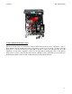
-Green Wire- Vehicle Speed Sensor (VSS) – Co-Pilot PIN #17
Locate the VSS (Vehicle Speed Sensor) wire at the vehicle’s PCM. Tap the Dark Blue W/Yellow
stripe wire at pin #59 on the PCM (located inside the engine compartment on the driver’s side of the
firewall, behind the wheel well) by soldering. Shield the tap from the elements.
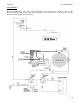
-Gray Wire- Exhaust Brake – Co-Pilot PIN #13 (Only for vehicles with Exhaust Brake)
Locate the exhaust brake solenoid. There should be 2 wires coming off of the solenoid. One wire
delivers power to the solenoid via a power switch mounted inside the cab. The other wire supplies
ground to the solenoid. The ground wire that comes from the solenoid to the ground on the engine must
be removed and connected to the gray wire that comes from the Co-Pilot module. The E-brake feature
of the Co-Pilot will only work with an exhaust brake that uses a solenoid to actuate it. We recommend
the use of a PACBRAKE with our Co-Pilot. Some exhaust brakes do not use a solenoid, instead they
use a computer module. In this case you will need to add a relay in the circuit to control the exhaust
brake or use the Co-Pilot as a stand-alone unit. See the supplied wiring diagram.