
Installation manual


10/3/2012 601-900-3224-INST
8
The other wires need to be run through the firewall to the engine or to the transmission
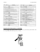
-Red Wire- +12V Power – Co-Pilot PIN #1
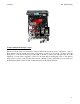
Connect the red wire of the Co-Pilot module by soldering to the red wire coming from pin #71 of the
PCM (located inside the engine compartment on the driver’s side of the firewall, behind the wheel well).
Make sure you protect the tap from the elements. If your kit came with a second red wire, you may
discard it.
-Orange Wire- MAP Sensor – Co-Pilot PIN #4- OPTIONAL
Connecting the Co-Pilot to the map sensor will cause the torque converter to unlock when the engine is
not producing boost. This will allow the engine RPM to increase before engaging the torque converter
clutch. However, when driving through rolling hills while towing, the constant clutch engagement and
disengagement can become unfavorable. With the orange wire unconnected the Co-Pilot will control
lockup purely on the vehicle speed setting.
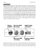
To control lockup with vehicle speed and boost pressure, locate the MAP sensor on the passenger side of
the engine near the heater box. Tap the light green with black wire. This wire can also be found at the
PCM in Pin #79 (Note: if the vehicle is a California or Canada vehicle the wire is in Pin #88 instead of
#79). Make sure the connection is sealed.
-White Wire- Overdrive – Co-Pilot PIN #5- OPTIONAL
This feature cancels overdrive every time the vehicle comes to a stop, requiring the driver to reactivate
overdrive each time. If you would like this feature, locate the OD (Overdrive) wire in the vehicle’s
wiring harness:
Tan w/ white stripe wire at pin #29 on the PCM (located inside the engine compartment on the
driver’s side of the firewall, behind the wheel well)
Run the white wire from the ATS Co-Pilot Module to the OD wire from the PCM or the steering
column and cut off any excess, but leave some slack. Solder the Co-Pilot white wire to the OD wire and
protect it from the elements.
-Black Wire- Ground (GND) – Co-Pilot PIN #9
Locate the Black wire coming from the vehicle’s PCM Pin #51. Tap this wire with the black Co-Pilot
wire by soldering. Shield the tap from the elements.
-Yellow Wire– PCM – Co-Pilot PIN #10 and -Blue Wire– TCC – Co-Pilot PIN #11
Locate the vehicle’s Torque Converter Clutch (TCC) wire coming at the vehicle’s PCM, the Purple w/
Yellow stripe wire at pin #54 on the PCM (located inside the engine compartment on the driver’s side of
the firewall, behind the wheel well)
Cut this wire and solder or attach a blue butt connector to the wire leading back to the transmission and
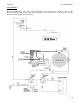
solder attach a blue butt connector to the wire heading to the vehicles computer (PCM). Reference the
supplied wiring schematic before cutting wire.