Rhein Tech Laboratories 360 Herndon Parkway Suite 1400 Herndon, VA 20170 http://www.rheintech.com APPENDIX H: Client: Alinco, Inc Model: DR-135TMkII Standards: FCC 15.121/IC RSS-215 Report #: 2002221 Date: January 31, 2003 MANUAL Please see the following pages.
VHF FM Mobile Transceiver DR-135T Instruction Manual ALINCO,INC. Head Office: Shin-Dai building 9th Floor 2-6, 1-Chome, Dojimahama, Kita-ku, Osaka 530-0004, JAPAN Phone:+81-6-4797-2136 Fax:+81-6-4797-2157 E-mail:export@alinco.co.jp Thank you for purchasing your new Alinco transceiver. This instruction manual contains important safety and operating instructions. Please read this manual carefully before using the product and keep it for future reference. Printed in Japan Copyright Alinco,Inc.
NOTICE / Compliance Information Statement This equipment has been tested and found to comply with the limits for a Class B digital device, pursuant to part 15 of the FCC Rules. These limits are designed to provide reasonable protection against harmful interference in a residential installation. This equipment generates, uses, and can radiate radio frequency energy and, if not installed and used in accordance with the instruction manual, may cause harmful interference to radio communications.
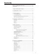
Contents Before operating the transceiver ...................................... 3 Introduction ........................................................................ 3 1. New and Innovative Features ........................................ 4 2. Standard Accessories .................................................... 5 3. Initial Installation ............................................................ 6 For a base station set up .......................................................................
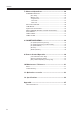
Contents 7. Advanced Operations .................................................. 26 SCANNING FUNCTION ...................................................................... [VFO Scan] ............................................................................. [Memory scan] ........................................................................ • Program scan ....................................................................... • Tone Scan .............................................................
Before operating the transceiver Attention • Do not remove the case or touch the interior components. Tampering can cause equipment trouble. • Do not use or keep the transceiver where it is exposed to direct sunlight, dusty places, or near sources of heat. • Keep the transceiver away from TV's or other equipment when it interferes with reception. • When transmitting for long periods of time at high power, the transceiver might overheat.
1. New and Innovative Features Your new radio features some of the most advanced functions and reliable engineering available anywhere. The ALINCO design philosophy is focused on developing innovative usable features, including the following: • Three different styles of display are available on a large LCD panel including frequency, channel number or 7 digit alphanumeric label. The dimmer (bright/dim) makes it easier to read the display at night.
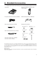
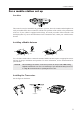
2. Standard Accessories Carefully unpack to make sure the following items are found in the package in addition to this manual: • Transceiver • Microphone EMS-53 or EMS-57 (with DTMF keypad) • DC power cable with fuse holder (UA0038) • Mobile mounting bracket. (FM0078Z) • Alarm cable A (with wire) (UX1259) • Hardware kit for bracket • Alarm cable B (extension use) (UX1260) • Theft Alarm stickers 2pcs. (PR0454) • Instruction manual (PS0349) Black screws (M4*8mm) 4pcs.
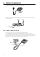
3. Initial Installation Connect the microphone to the front panel of the transceiver. Connect antenna port to a 50 ohm antenna that covers the two-meter band, using good quality 50 ohm coaxial cable. Microphone External speaker (if used) Antenna rear panel For a base station set up The Transceiver requires a 12-13.8VDC negative grounded power source. Use a regulated power supply capable of providing continuous current of 12A or more.
3. Initial Installation For a mobile station set up Location The transceiver may be installed in any position in your car, where the controls and microphone are easily accessible and it does not interfere with the safe operation of the vehicle or the performance of the set. If your vehicle is equipped with air bags, be certain your radio will not interfere with their deployment. If you are uncertain about where to mount the unit, contact your vehicle's manufacturer.
3. Initial Installation External power supply control & power lamp functions ACC terminal Cigar-Plug connection Ext. Power jack Battery DC cable Be sure the vehicle has a negative-ground, 12VDC electric system before installation. Connect the provided DC cable directly to the battery as shown below to minimize any possible ignition noise. Be sure the vehicle has a large capacity battery as the use of the transceiver may overload the electric system of the vehicle.
4. Part Names and Functions Front Panel 10 2 11 1 12 4 5 6 7 8 9 3 •Primary Functions No. 1 2 3 4 5 6 7 8 9 10 11 12 Key PWR Volume knob Dial FUNC/SET V/M/MW MHZ/SHIFT TS/DCS/LOCK CALL/H/L SQL/D DATA Terminal TX Light indicator Mic. Connector Function Power turns ON / OFF whenever switch is pressed. Adjusts the volume level. Changes the frequency, memory channel and scan direction. Sets the function mode to access additional settings. Switches between VFO mode and memory mode.
4. Part Names and Functions •Functions that can be activated while pressing the FUNC Key No. 1 5 6 7 8 9 Key PWR V/M/MW MHZ/SHIFT TSDCS/LOCK CALL/H/L SQL/D Function Reset to factory default settings. Erase the memory. Switches to wide / narrow mode reception. Sets the auto dialer. Accesses the clone function mode. Accesses the power supply voltage indication mode. • Functions that require continuous pressing to be activated. No.
4. Part Name of Functions Display 19 18 17 16 15 14 13 12 11 10 1 9 2 5 3 6 7 8 4 No. 1 2 3 4 5 6 7 8 9 10 11 12 13 14 15 16 17 18 19 Key SQL M Function Appears when setting the squelch level. Appears when in memory mode. Indicates the memory channel number in memory mode. .Decimal point Appears when setting the theft alarm function. .Decimal point Appears when setting the skip level. .Decimal point Indicates the decimal point of frequency and the scanning function.
4. Part Names and Functions Microphone Standard No. 1 2 3 4 Option Key UP DOWN PTT DTMF Function Increase the frequency, memory channel number, or setting value. Decrease the frequency, memory channel number, or setting value. Press the PTT(Push-To-Talk)key to transmit. DTMF tone keys Set to DTMF when you don’t want to operate remote conDTMF / REMOTE trol functions. So that DTMF keys do not function except 5 Switch during transmit to send DTMF codes manually.
5. Basic Operations Turning the unit on and off PWR key Press the power switch or turn the ignition key to ACC or ON position according to the option selected during installation. Press the power switch again or turn the ignition key to OFF position to turn off. Audio Volume level setting Minimum volume Maximum volume Rotate the VOL knob clockwise to increase the audio level, counterclockwise to decrease. Set it at the desired level.
5. Basic Operation VFO mode VFO tuning is set as a default mode at the factory. VFO (variable frequency oscillator) allows you to change the frequency in accordance with the selected channel step as you rotate the main dial or by using the UP/DOWN keys on the microphone. VFO mode is also used to program the data to be stored in the memory channels or to change the parameter settings of the transceiver. 1. Identify the current mode by checking the display.
5. Basic Operation Changing the channel step 1. Be sure the unit is in VFO mode. Refer to page 21 to enter into the SET mode. 2. Select the channel step parameter setting using the tuning knob. The current channel step will be displayed as below. 3. Press PTT or any one of the keys except SQL on the front panel to enter the desired step into the transceiver’s memory. The display will then return to the original status.
5. Basic Operation CTCSS / DCS setting Many repeaters require a CTCSS tone or a DCS code encode setting as a “key” to access the system, so-called “selective-calling”. Sometimes, CTCSS or DCS decode features are used on the output of a repeater so they can be used as a squelch. In this mode, regardless of the main squelch status, the audio can be heard ONLY when the matching tone/code signal is received.
5. Basic Operation Memory Mode The memory mode on this transceiver provides up to 100 channels (0-99), 1 call (quick recall ch) and a pair of program-scan “edge memory” channels for quick, easy access to the preprogrammed frequencies with different parameter settings. 1. Press V/M key. M icon appears on the display to indicate that the unit is in the memory mode. Repeat to switch the mode between VFO and memory. 2.
5. Basic Operation 4. While F icon is on the display, press MW key. The VFO settings are copied to the memory channel and a beep will sound. The memory channel can be over-written if a previously programmed channel is selected (the memory channels shown with a stable M icon). 5. To program the CALL channel (quick recall) select the channel shown with CH-C on the display. Save Ch99 to store the setting used for the Alarm operation, which will be explained later.
5. Basic Operation CALL mode This is a memory mode that allows the transceiver to quickly recall the assigned memory channel by simply pressing the CALL key, regardless of the current status of the unit. 1. Press CALL key. The C icon appears on the display and the transceiver enters the CALL mode. In this mode, the main dial or the UP/ DOWN keys cannot change the frequency or memory channels. 2. Press CALL key again or press V/M key to exit CALL mode. 3. No scan functions are available in CALL mode.
5. Basic Operation To transmit 1. Select the desired frequency. Be sure that you are authorized to operate on the selected frequency. Check the system and monitor the frequency to make sure that you are not going to disturb any ongoing communications. 2. Select the output power. Press FUNC key and then press CALL key while F icon is on the display. As the CALL key is pressed, the output power changes among 3 levels. The Lo icon stands for LOW power setting, Mi for MEDIUM power.
6. Parameter Setting Mode IMPORTANT: Please read the following pages thoroughly prior to the change of any parameters. THE PARAMETERS CANNOT BE SET WITHOUT ENTERING THE SET MODE. By entering the Parameter Setting mode, some of the radio’s operating parameters can be changed to suit your application. The following is the Selectable Parameters’ Menu. Note: The Alphanumeric Channel Tag setting will not appear in the menu until memories have been programmed first! To use the Parameter Setting mode 1.
6. Parameters Setting Mode Channel Step setting: This is to select the channel step to be used in the VFO mode. Refer to the chart below for the relation of the actual step frequency and how it is displayed. Scan Type This is to select the scan resume condition. TIMER setting allows the radio to resume scanning after 5 seconds, regardless of the signal receiving status. BUSY setting resumes scanning when the received signal is gone. The scan mode is explained later.
6. Parameters Setting Mode Time-Out-Timer The TOT feature is popular in repeater systems. It prohibits the users from transmitting on the repeater after a certain period of time has elapsed. By setting this function and activating it according to the repeaters’ requirement, the radio alerts the user by a beep 5 seconds prior to time-out. When the time is expired, transmitting stops and the transceiver automatically returns to receiving mode. This avoids the repeater going into its TOT mode.
6. Parameters Setting Mode APO-Auto Power OFF This feature will automatically shut off the transceiver. It is useful for mobile operation to avoid draining the car battery. If there is no activity or use of the radio, it will turn off automatically after 30 minutes followed by a beep sound. 1. Default is APO-OFF. 2. Rotate dial to select APO-ON to activate the function.
6. Parameters Setting Mode Alphanumeric Tag The memory channels stored in the memory-mode can be displayed with an alphanumeric tag instead of the default frequency display. Program the memory channel first. There are 67 characters available including A-Z, 0-9. 1. Enter the set mode while the unit is in memory mode. 2. Select alphanumeric tag setting by rotating the main dial or pressing the UP/DOWN keys. The display shows [A] flashing. 3. Rotate the main dial to select a character.