Contents Features ··········································································································5 NOTICE···········································································································6 Precautions ·····································································································7 Request and Agreement·················································································7 Accessories ········································
Scan Function ·······························································································26 VFO Scan ································································································27 Program Scan ·························································································27 Preset Scan ·····························································································28 Memory Scan ···································································
Features The DJ-X3 is a wide band communication receiver which has various functions in a small package. Easy operation with a simple key arrangement allows you to access a wide range of communications. The DJ-X3 has the following features. Types of Memory The DJ-X3 has different types of memory functions.
NOTICE This equipment has been tested and found to comply with the limits for a Class B digital device, pursuant to part 15 of the FCC Rules. These limits are designed to provide reasonable protection against harmful interference in a residential installation. This equipment generates, uses, and can radiate radio frequency energy and, if not installed and used in accordance with the instruction manual, may cause harmful interference to radio communications.
Precautions No warranty is made on the effectiveness of the "Bugging Detector" function. The function should be considered experimental and for educational or entertainment use. Use of the descrambling function may not be permitted in certain jurisdictions. Check with the regulations that apply in your area before using. Request and Agreement · This product is manufactured and shipped under strict quality control.
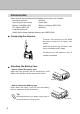
Accessories Open the box and check that the following accessories are included. · Instruction manual · Antenna · Belt clip (with one screw) · Hand strap · Battery case (EDH-31S) · Battery recharger (EDC-105) · AC adapter (EDC-92) · Warranty · Frequency data list · NiMH (Nickel Metal Hydride) battery pack (EBP-52NS) ■ Connecting the Antenna Connect the antenna to the SMA antenna connector at upper left corner. Hold the antenna by its base, and turn it clockwise until it stops.
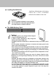
■ Loading the Batteries Load three AA batteries in the battery case in the "+" and "-" orientation marked at the bottom of the case. Caution! · Do not use NiCad AA batteries on the market. · Use new batteries of the same type and brand. · Use high capacity of alkaline batteries. ■ The NiMH Battery Pack Battery Pack Type EBP-52NS (3.6V-500mAh) Charging Time About 10 hours Caution! · The battery pack is not charged when shipped. It must be charged before use.
■ Prevent Short Circuiting the Battery Pack Be extra cautious when carrying the battery pack; short-circuiting will produce surge current possibly resulting in fire. Terminals DON'T carry with metals of any type, e.g. chains. DON'T carry the NiMH battery pack inside bags of metal plated interior. Do enclose inside a non-conductive enclosure. (bags or handkerchief made only of nonconductive material) 10 DON'T place in the proximity of metals or conductives, e.g. nails, chains.
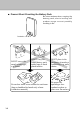
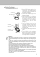
■ Battery Recharger · Recharging with the EDC-105 Power plug AC adapter plug Terminals (rear side) Terminals on the rechager 1 3 2 Lever(1〜3) 1. Mount NiMH battery pack on the transceiver. (The NiMH battery pack itself is also mountable on the battery recharger.) 2. Connect AC adapter plug to the battery recharger. 3. Select the position 1 to 3 with the lever on the recharger and adjust the battery pack to fit with it. (According to a type of battery pack, position of the lever changes.) 4.
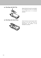
■ Attaching the Belt Clip Attach the belt clip on the rear side of the transceiver with an included screw. Make sure it is screwed properly. ■ Attaching the Hand Strap Attach the hand strap through a ditch between the belt clip and the transceiver as shown in the illustration on the left.
Chapter 1 Names and Functions of Parts External View 1 ■ Front Names and Functions of Parts Display Displays the frequency and other information. (P.16) Speaker Thin built-in speaker POWER SCAN Keyboard For changing the mode and various settings. (P.15) SCRT V/P/M MW BANK 1M/10M DJ-X3 WIDE BAND COMMUNICATION RECEIVER ■ Top Antenna connector For connecting the included antenna. (P.8) Earphone jack For connecting of an earphone.
■ Side 1 Names and Functions of Parts ENT FUNC KL MONI ST SK [FUNC/ENTER] key Use this key to set and execute several settings. Besides, hold this key down for about one second, key-lock function is on. (P.35) DC IN [MONI(ST/SK)] key While holding this key down, squelch temporarily opens. Besides, use for Mute function. (P.19) DC-IN Terminal for connecting an external DC power supply.
Keyboard 1 Names and Functions of Parts POWER ① SCAN ② SCRT V/P/M ③ MW BANK ④ 1M/10M DJ-X3 WIDE BAND COMMUNICATION RECEIVER ① Key [POWER] key ② [SCAN (SCRT)] key ③ [V/P/M (MW)] key ④ [BANK (1M/10M)] key Function Turn the power on/off. Executes scanning. (P.26) When "F" is displayed, used for Descrambling. (P.32) Switches the operating mode. (P.21) When "F" is displayed, programs and clears the Memory channels. (P.24,25) Switches the Preset and Memory mode. (P.
Display 1 In the illustration below, all indicators are displayed. Names and Functions of Parts ① ② F ⑫ ⑬ ③ ④⑤ ⑭ T SQ DCS W SKIP A ⑦ ⑧ ⑨ ⑥ VOX ATT 75 50 25 B ⑯ ⑩ ⑮ ⑪ Descriptions ① ② Appears when you press the [FUNC/ENTER] key. Flashes when displaying over 1000MHz frequency. (Indicates a digit of 1000MHz.) Indicates the modulation mode. Appears "W" when WFM radio is ③ selected and "A" when AM radio is selected. When FM radio is selected, nothing appears.
Chapter 2 Basic Operation Power Switch Hold the POWER switch down for a second. "HELLO" will appear on the display. (The indication may be different from the illustration below depending on the version: North America or Europe.) Basic Operation POWER [POWER] key SCAN SCRT V/P/M MW BANK 1M/10M To turn the power off, hold the POWER switch down until the indication disappears. Adjusting the Audio Volume 1 Press the [VOL/SQL (SET)] key. (dial) "voL" will appear on the display.
Adjusting the Squelch The squelch silences the DJ-X3 except for signals above a certain level. Squelch eliminates noise when the DJ-X3 receives less than a certain level. "To unmute the squelch" means that the DJ-X3 receives a signal and reproduces the sound. Conversely, "to close the squelch" means that the DJ-X3 does not generate audio because of insufficient signal level.
■ Monitor Function The Monitor function temporarily unmutes the squelch. This is useful when the desired signal is weak or intermittent. This function is activated when the status of the [MONI(ST/SK)] key is set as Monitor function in the Set mode. For more information, see "Setting Operation of the MONI key." (P.46) [MONI(ST/SK)] key POWER SCAN SCRT V/P/M · PUSH: Squelch unmutes while holding the [MONI(ST/SK)] key down. When release the key, squelch goes back to be normal as you set before.
[MONI(ST/SK)] key 2 POWER Basic Operation SCAN B SCRT V/P/M · PUSH: Mute function is on while holding the [MONI(ST/SK)] key down. When release the key, the function is off and receiving signals and beep sound unmute. · HOLD: Mute function is on and it remains the status once press the [MONI(ST/SK)] key. Press the key again, then the function is off and receiving signals and beep sound unmute. Tip Select either Monitor function or Mute function.
■ Switching Modes Every press of the [V/P/M (MW)] key changes the operating mode as shown below. 2 VFO mode V/P/M MW MW Preset mode Basic Operation V/P/M Memory mode V/P/M MW Tip When nothing is programmed in Memory mode, Memory mode is skipped and switches between VFO mode and Preset mode in turn.
Setting the Frequency ■ In VFO Mode Rotating the dial increases or decreases frequency for a tuning step. To increase/decrease the frequency by 1MHz-step, press the [BANK(1M/10M)] key one time and rotate the dial one click each. To increase/decrease the frequency by 10MHz-step, press the [BANK(1M/10M)] key once again and rotate the dial one click each. In 1MHz and 10MHz mode, each digit of 1MHz or 10 MHz number flashes.
■ In Memory Mode 1 Select a bank by pressing the [BANK(1M/10M)] key. 2 Bank No. Channel No. 2 Basic Operation POWER SCAN SCRT V/P/M MW BANK 1 2 1M/10M B Select a channel by rotating the dial. It is not possible to select a channel which is not programmed. Memory Function This function allows you to program the frequently used frequencies, and call them up. A programmed frequency is called a channel.
■ Programming a Channel 1 In VFO mode, select the frequency which you want to program. 4 2 Bank No. Channel No. F 2 Basic Operation POWER SCAN SCRT 1.5 3 V/P/M MW BANK 1M/10M B 2 Press the [FUNC/ENTER] key. "F", bank No., and channel No. will appear on the display. 3 Select a bank by pressing the [BANK(1M/10M)] key. Each bank No. corresponds to the following bank.
■ Erase the Channel 1 2 Switch to the Memory mode by pressing the [V/P/M (MW)] key. 3 Press the [FUNC/ENTER] key. "F" will appear on the display. Select a channel which you want to erase. For more information, see "In Memory Mode." (P.23) 2 Basic Operation Bank No. Channel No. 3 POWER SCAN SCRT 1.4 V/P/M MW BANK 1M/10M 4 B Press the [V/P/M (MW)] key. The channel will be erased. Tip You can clear all the programmed channels at one time. For more information, see "Resetting." (P.
Scan Function The scan function periodically changes the frequency to search for a signal. The DJ-X3 has four types of scan functions. VFO scan ······································Scans the entire band in VFO mode. Program scan································Scans a specified range of frequencies. The upper limit and lower limit of the range need to be set in advance. Preset scan ··································Scans the entire band in Preset mode.
■ Program Scan This function scans a specified range of frequencies. Before operating this function, you need to specify the upper and lower frequency limits. These frequencies are called a "Program channel", and the DJ-X3 has 20 pairs of program channels. Set the combination of upper and lower limits. (i.e. A00 and B00, or A01 and B01) For more information, see "Programming a Channel." (P.24) Switch to the VFO mode by pressing the [V/P/M (MW)] key. 2 Press the [SCAN(SCRT)] key.
■ Preset Scan 2 1 Switch to Preset mode by pressing the [V/P/M (MW)] key. 2 Select AM radio, FM radio, or TV by pressing the [BANK(1M/10M)] key. Basic Operation W POWER SCAN 3 SCRT V/P/M 1 MW BANK 2 1M/10M Flashes 3 Press the [SCAN(SCRT)] key. Preset scan starts, and ". (decimal point)" flashes on the display. Scanning pauses when receiving a signal. ■ Memory Scan This function scans the specified banks or all banks in the Memory mode. There are three types of Memory scan.
To operate Memory scan: 1 Switch to Memory mode by pressing the [V/P/M (MW)] key. 2 Press the [SCAN(SCRT)] key. Type of Memory scan will appear on the display. 2 Basic Operation 3 POWER 2 1 SCAN SCRT V/P/M MW BANK 1M/10M Type of Memory scan 3 Rotate the dial as holding the [SCAN(SCRT)] key, and select a type of Memory scan.
Setting the Tuning Step The tuning step sets the increment/decrement of each click of the dial when adjusting the frequency in VFO mode. 2 Basic Operation 1 Switch to VFO mode by pressing the [V/P/M (MW)] key. 2 Press the [FUNC/ENTER] key. "F" will appear on the display. 3 Press the [MONI(ST/SK)] key. The currently selected tuning step will appear on the display. The default setting is AUTO. ("AUto") 4 F 2.
Memory Skip This function is for skipping the specified memory channel(s) when executing the Memory scan. Switch to Memory mode by pressing the [V/P/M (MW)] key. 2 Call up the memory channel you want to skip. 3 Press the [FUNC/ENTER] key. "F" will appear on the display. 3 2 Basic Operation 1 F 4 POWER SCAN SCRT V/P/M 1 MW BANK 1M/10M 4 Press the [MONI(ST/SK)] key. The setting will be completed.
Chapter 3 Convenient Functions on DJ-X3 Descrambling This function returns scrambled voice to normal reception. 3 Select the frequency of the scrambled voice. 2 Press the [FUNC/ENTER] key. "F" will appear on the display. 3 Press the [MONI(ST/SK)] key. Descrambling function starts operating, and "*" at the bottom left of the display flashes. Decode No. for scrambling will appear on the display. Convenient Functions on DJ-X3 1 4 2 POWER 3 SCAN SCRT V/P/M MW BANK 1M/10M Flashes 4 Decode No.
Bugging Detector The DJ-X3 detects a bugging signal by scanning frequencies in the programmed memory banks. When a listening microphone is found, the DJ-X3 notifies you with its display and a warning sound. Caution! Be sure to remove the earphone when detecting Bugging. 1 2 1 POWER SCAN SCRT V/P/M MW BANK 1M/10M Appear When a bugging signal is found, "dc" flashes on the display, and scanning stops. F Flashes ATT B 2 Press the dial (the [VOL/SQL(SET)] key) down to adjust the audio volume.
Caution! · Operate in a quiet environment where doors and windows are closed. It is hard to find a listening microphone in a noisy environment. · Depending on the modulation setting, this function may not work correctly. · When the battery voltage is low, this function does not work normally. Be sure to recharge the battery pack completely, load new AA batteries, or supply sufficient voltage from the DC power supply.
Keylock To prevent incorrect or unauthorized operations, you can lock the keys. The following operations can be used while the keylock is ON. · Monitor function · Mute function · Adjusting the audio volume and squelch · Canceling the keylock · Turning the power ON/OFF 1 3 Appears [FUNC/ENTER] key POWER SCAN SCRT V/P/M MW BANK 1M/10M How do you cancel the keylock? Hold down the [FUNC/ENTER] key for a second while the keylock is ON. The keylock will turn OFF, and the key icon will disappear.
Resetting You can reset programmed memory channels and settings. There are two types of reset; Partial reset and All reset. Partial reset ···································Programmed memory channels remain, and the other settings are reset. All reset ·········································All the memory channels and settings are reset. However, Preset channels (AM radio/FM radio/TV) cannot be reset.
The Set Mode Function This Set mode allows you to customize the DJ-X3 for your particular application. The following items can be set in Set mode. ATT (Attenuator) function (P.38) Setting the antenna (P.38) Selecting the modulation mode (P.39) Selecting from stereo and monophonic (P.40) Setting Bugging Detector sensitivity (P.40) Setting bank link (P.41) Lamp function (P.42) Setting the scan mode (Timer scan/Busy scan) (P.42) APO (Auto Power Off) function (P.43) BS (Battery Save) function (P.
■ ATT (Attenuator) Function This function attenuates strong signals on nearby channels. Use this function when the received signal is influenced by a strong signal. ATT function attenuates about 20 dB in received signal. In Set mode, select "Att." F 3 Convenient Functions on DJ-X3 · Select ON/OFF by rotating the dial. · The default setting is OFF. ■ Setting the Antenna You can select the antenna depending on the frequency you wish to receive. The DJ-X3 has four types of antennas.
In Set mode, select the type of antenna. F 3 Tip · If each type of bar antenna sets to be OFF, external antenna, which is attached to the DJ-X3, receives a signal. · When using the earphone antenna, a signal may be unstable depending on the position of the earphone cord. · When using the bar antenna, a signal may be unstable depending on the condition of the frequency. ■ Selecting the Modulation Mode You can select a modulation mode from AM, FM, and WFM. In Set mode, select "wAvE.
■ Selecting from Stereo and Monophonic In Set mode, select either "mono" or "StErEo." F W 3 Convenient Functions on DJ-X3 · When rotating the dial, the setting of "mono" and "StErEo" changes alternately. · Stereo mode is available only when the modulation mode is set to WFM. Receive a signal with monophonic mode even stereo mode is selected when AM or FM is selected. · The default setting is stereo mode. ■ Setting Bugging Detector Sensitivity You can select the sensitivity when detecting a bugging.
■ Setting Bank Link This is the setting for the "Bank link scan", which scans specified multiple banks. You can select up to 5 banks from 10 (0 to 9) programmed banks. In Set mode, select "bL." F 3 · Select bank link No. by rotating the dial. · Select a bank to link by pressing the [BANK(1M/10M)] key. One bank can be assigned to each bank link No. 0-4. Tip · When only one bank is set to the bank link, if you execute the bank link scan, only one bank will be scanned.
■ Lamp Function This function sets the display backlight ON or OFF. When ON is selected, an operation of any key turns ON the backlight, and it automatically turns OFF after 5 seconds. In Set mode, select "LAmP." F 3 Convenient Functions on DJ-X3 · Select ON/OFF by rotating the dial. · The default setting is ON. ■ Setting the Scan Mode (Timer Scan/Busy Scan) You can set the scan-resume condition. While executing the scan, if the DJ-X3 receives a signal, scanning will pause.
■ APO (Auto Power Off) Function This function automatically turns the power off if there is no key operation for a specified period of time. Right before cutting the power off, beep sound will go off. Select the time from 30, 60, 90 minutes, and OFF. When OFF is selected, this function does not work. In Set mode, select "APO." 3 F Convenient Functions on DJ-X3 B · Select ON/OFF by rotating the dial. · The default setting is OFF. Tip APO function does not operate while scanning.
■ BS (Battery Save) Function This function extends battery life. If there is no key operation for five seconds, the internal power rapidly cycles between ON and OFF. In Set mode, select "bS." F 3 Convenient Functions on DJ-X3 · Select ON/OFF by rotating the dial. · The default setting is ON. ■ Overwrite Memory Setting To prevent from overwriting memory channels by mistake, set whether disable or enable to overwrite. In Set mode, select "ow." F · Select ON/OFF by rotating the dial.
■ PRIO (Priority) Watch Function This function monitors two frequencies alternately. Every five seconds, the DJ-X3 momentarily switches from the frequency in the VFO mode to the frequency in the Priority channel. In Set mode, select "Pr." F 3 Priority channel Tip · Scanning is not available during Priority Watch. · If the DJ-X3 received a signal of the Priority channel, receiving time will be extended for 2 seconds.
■ Setting Operation in the Monitor and Mute Function Select operation of the [MONI(ST/SK)] key when Monitor and Mute function is set. In Set mode, select either "HoLd" or "PUSH." F 3 Convenient Functions on DJ-X3 · Select either "HoLd" or "PUSH" by rotating the dial. · When "PUSH" is set, Monitor and Mute function is activated while holding down the [MONI(ST/SK)] key. · When "HoLd" is set, Monitor and Mute function is activated every time press the [MONI(ST/SK)] key down. · The default setting is PUSH.
Cloning When using Clone function, all memories and the settings of one DJ-X3 (master) can be copied to another DJ-X3 (slave). 1 2 Turn OFF both DJ-X3s. (master and slave) Connect the earphone jacks on both master and slave DJ-X3s with the cloning cable. Convenient Functions on DJ-X3 3 3 Connect to the earphone jack of the slave unit of the DJ-X3. Connect to the earphone jack of the master unit of the DJ-X3. Turning on both master and slave power as holding the [BANK(1M/10M)] key down.
4 Press the dial (the [VOL/SQL(SET)] key) on the master side of the DJ-X3. Cloning starts. "Sd □□□□" appears on the master DJ-X3's display, and "Ld □□□□" appears on the slave DJ-X3's display. (□□□□ changes constantly.) 3 Convenient Functions on DJ-X3 (Master) (Slave) When cloning is completed, "PASS" appears on both DJ-X3s' displays. To return to normal operation, turn the power off, and then turn it on again. Caution! · Do not disconnect the cable while cloning.
If "comErr" appears on the display... If a communication error occurs, "comErr" will appear on both DJ-X3s' displays. Make sure the cloning cable is connected to each side of the earphone jack properly. When pressing the dial (the [VOL/SQL(SET)] key) down on the master side of the DJ-X3, restart cloning.
Chapter 4 Appendix Troubleshooting Please check the list below before concluding the DJ-X3 is faulty. If a problem persists, reset the DJ-X3. This can sometimes correct erroneous operation.
Specifications ■ General : : : : : : Ground Current consumption : : Temperature range Frequency stability Dimension : : : Weight : 0.1 - 1299.995 MHz 0.1 - 1299.995 MHz A3 (AM),F3 (FM, WFM) 50Ω SMA DC 3.6V - DC 6V (external input voltage DC 4.5V - DC 16V) Negative ground Reception : approx. 75 mA Battery save (1 : 4) : approx. 39 mA –10 ~ +60°C (+14 ~ +140°F) ±5 ppm (–10 ~ +60°C / +14 ~ +140°F) W:56 H:102 D:23 mm (without projections) (W:2.20 H:4.01 D:0.90 in.) Approx.