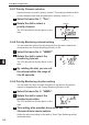
8. Set Mode Configurations 8. Set Mode Configurations The Set mode allows you to change the DJ-X30's functions and default settings as desired. 8-1 Configuring Values/Parameters of Set Mode Menu Items 1 Press the [FUNC] key to display the icon on the LCD. 2 Press the dial once to switch to Set mode. 3 Every time you press the dial, the setting item (Set menu item) is changed. 8 • When you press the [MONI] key, the items are displayed in reverse order.
8. Set Mode Configurations 8-2 Set Mode Configurations Details of each item of the Set mode menu are as follows. 8-2-1 Attenuator (ATT) function setting Use this function when the receiving signal is interfered with by strong signals from nearby channels. When activated, this function weakens the reception level of the target signal. However, it also makes unnecessary signals difficult to receive, so that the target signal may become distinctly audible. The attenuation level is about 20 dB.
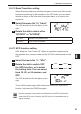
8. Set Mode Configurations 8-2-3 AM Radio Bar-antenna setting You can choose either the built-in bar-antenna or an external antenna to receive AM radio signals. The bar-antenna covers the range of 100 kHz to 3 MHz including the AM radio band. 1 Select Set menu No. 3, "AbAr". The LCD should look like the figure on the right. 2 To use an external antenna, rotate the dial to change the display from "ON" to "OFF". The default is set to use the built-in bar-antenna.
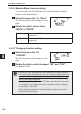
8. Set Mode Configurations 8-2-5 Lamp Operation setting You can set the operation of the backlight of the LCD. Using the backlight frequently increases the drain on the battery. 1 Select Set menu No. 5, "LAMP". The LCD should look like the figure on the right. 2 Rotate the dial and the backlight operation changes as shown in the figure. 5-SEC ON OFF ALLOFF OFF The backlight does not turn ON. 5-SEC When you operate the DJ-X30, the backlight turns ON for 5 seconds.
8. Set Mode Configurations 8-2-7 Priority Channel selection Use this function to select a priority channel. This setting is effective when priority channels have been programmed in Memory mode (+P. ••). 1 Select Set menu No. 7, "Prio". 2 Rotate the dial to select a Channel priority channel. The LCD should look like the figure on the right.
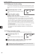
8. Set Mode Configurations 8-2-10 Band Transition setting When the setting frequency reaches the upper or lower end of the current band during scanning or dial operation in the VFO mode, you can select whether to return to the other end of the same band, or to move to the next band. 1 Select Set menu No. 10, "bAnd". The LCD should look like the figure on the right. 2 Rotate the dial to select either "ROTATE" or "ACROSS". ROTATE Remain in the same band. ACROSS Move to the next band.
8. Set Mode Configurations 8-2-12 Battery-save function setting This function automatically turns ON/OFF the DJ-X30 frequently in order to save power consumption during standby and extend battery operation time. 1 Select Set menu No. 12, "bS". The LCD should look like the figure on the right. 2 Rotate the dial to switch between "ON" and "OFF". 8 When this function is set to ON, "BS" appears on the LCD. • The default is set to ON. It is not necessary to turn the function OFF in normal operation.
. Set Mode Configurations 8-2-14 Bell function setting The Bell function informs you with a bell sound when a signal is received. 1 Select Set menu No. 14, "bELL". The LCD should look like the figure on the right. 2 Rotate the dial to switch between "OFF" and "ON". When this function is set to ON, the icon appears on the LCD. When a signal is received, the icon blinks and a bell sounds.
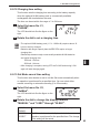
8. Set Mode Configurations 8-2-16 Monitor/Mute function setting You can set the role of the [MONI] key, to either activate the Monitor function or the Mute function. 1 Select Set menu No. 16, "Moni". The LCD should look like the figure on the right. 2 Rotate the dial to select either "MONI" or "MUTE". MONI When the [MONI] key is pressed, the squelch opens temporarily. MUTE When the [MONI] key is pressed, sound is muted temporarily. 8-2-17 Charging function setting 8 1 Select Set menu No.
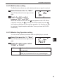
8. Set Mode Configurations 8-2-18 Charging time setting This function sets the charging time according to the battery capacity when the optional Ni-MH battery pack or commercially-available rechargeable AA-size batteries are used. The time can be set within the range of 1 to 24 hours. 1 Select Set menu No. 21, "CHGtiM". The LCD should look like the figure on the right. 2 Rotate the dial to set a charging time. • The optional Ni-MH battery pack (1.
8. Set Mode Configurations 8-2-20 Write-protect (memory protection) function setting You can enable editing (overwriting or deleting) for the channel data programmed for the Memory mode. 1 Select Set menu No. 23, "ProtCt". The LCD should look like the figure on the right. 2 Rotate the dial to switch between "ON" and "OFF". ON Write-protect is enabled. You cannot edit the programmed data in the memory. OFF Write-protect is disabled. You can edit the data in the memory.
8. Set Mode Configurations 8-2-21 Skip-scan Operation setting You can select whether to skip the frequency programmed to the skipsearch memory channel and the memory channel specified for skip operation. The frequencies programmed to the skip-search memory channel are skipped during the VFO scan, programmed scan, and preset scan (excluding TV frequencies). The memory channels specified for skip operation are skipped during the memory scan.
8. Set Mode Configurations 2 Rotate the dial to display the functions which can be assigned to the key one by one. You can select a menu item from the following: Menu No.
8. Set Mode Configurations 8-2-23 Function assignment for remote controller buttons This menu is available only when the optional remote controller EPS-12 is used. You can assign the functions listed in the table below to the remote controller buttons as desired. The remote controller has four buttons for function assignment: A through D. 1 Use Set menu Nos. 26 through 29 to assign functions to remote controller buttons A through D respectively. The operation is common to all buttons.
9. Channel Display Mode 9. Channel Display Mode This mode displays only a bank and a channel number instead of a frequency in the Memory mode. Some other functions are also disabled. 1 Program frequencies into the memory beforehand. 2 Set the Memory mode to ON and turn the power OFF. 3 Turn the power ON while Bank holding down the [MONI] and keys simultaneously. The LCD should look something like the figure on the right.
10. Using the Optional Remote Controller 10. Using the Optional Remote Controller 10-1 Using the Remote Controller 10-1-1 Top/Bottom/Front panels (5) (1) (2) (3) (4) No. Item Description (1) Earphone jack Earphone output jack. Connect earphones or other output devices. (2) Operation button A Used as the V/P/M key. (3) Operation button B Used as the BAND key. (4) Earphone cord Plug this cord into the earphone jack of the DJ-X30.
10. Using the Optional Remote Controller 10-2 Connecting the Remote Controller The following figure shows the connection of the remote controller. Connect commercially-available earphones/headphones. Plug into the audio input jack of the remote controller. Commercially-available stereo mini-plug cable (ø3.5 mm). Plug into an MP3 player or other portable audio player. 10 Plug into the DJ-X30. 10-3 Remote Controller Functions • Both monaural and stereo earphones/headphones can be used.
11. Cable-clone and PC Connection Functions 11. Cable-clone and PC Connection Functions The Cable-clone function copies data from one DJ-X30 to another DJ-X30. By connecting two DJ-X30 units with a cable, you can copy the information (including memory data) specified in the sending unit (herein referred to as “Master”) to the receiving unit (herein referred to as “Slave”).
11. Cable-clone and PC Connection Functions 11-2 Receiving Data Use the following procedure to copy data from another DJ-X30 or to receive data edited on a PC. 1 Turn OFF the Slave and connect the stereo mini-plug cable to its earphone jack. Commercially-available 3-pole stereo mini-plug cable can also be used. 2 While holding down the [MONI] key, press the [PWR] key to turn ON the Slave. "CLONE" appears on the LCD and the Slave enters Clone mode. 3 Wait until the Master DJ-X30 or PC sends data.
11. Cable-clone and PC Connection Functions 11-3 Transferring Data The procedure below does not necessitate using the PC Connection function. 1 Turn OFF the Master and connect the stereo mini-plug cable to its earphone jack. 2 While holding down the [MONI] key, press the [PWR] key to turn ON the Master. "CLONE" appears on the LCD and the Master enters Clone mode. 3 While "CLONE" is displayed The number decreases. on the LCD, press the dial.
12. Reset Function 12. Reset Function • Before resetting the DJ-X30, be sure to check the memory protection CAUTION function settings. Resetting the receiver with the Write-protect (memory protection) function (+P. ••) in OFF state deletes all of the factory default data and user-programmed data. • You cannot restore data after it is deleted. The Reset function resets all values and parameters including the Set mode settings to the initial (factory default) settings.
12. Reset Function 12-2 Default Settings List of data after resetting (Factory default parameters) Frequency VFO mode, 145.000 MHz Volume level 20 Squelch level 3 Preset mode 76.1MHz Scan VFO scan Memory scan SINGLE scan Tuning step frequency AUTO CTCSS tone frequency 88.
12.
13. Maintenance and Reference 13. Maintenance and Reference 13-1 Troubleshooting Please check the list below before concluding that the receiver is faulty. If a problem persists even after performing the actions below, try resetting the receiver. This may correct erroneous operations. Symptom Nothing appears on the LCD Possible Cause Poor battery contact when you turn the power ON. Action Check that the battery terminals are clean.
13. Maintenance and Reference 13-2 Optional Accessories List • Soft Case (ESC-44) • Curl-Cable Earphone (EME-26) • Cigar DC/DC Converter (EDH-33) • Trickle Charger (EDC-154A) • Ni-MH Battery Pack (EBP-57N: 1.2 V-1800 mAh x 2) • Remote Controller (EDS-12) • PC Programming Cable (ERW-4C: for serial port connection) • PC Programming Cable (ERW-7: for USB connection) 13-3 Table of Available CTCSS Tones The table below shows the CTCSS tones available for the Tone Squelch function.
14. Index 14. Index NUMBER 10M Hz/1 MHz UP/DOWN................................ 27 A AC adapter.................................................. 14, 15 Accessories................................................... 2, 12 All-bank scan..................................................... 35 AM..................................................................... 47 APO................................................................... 60 Attenuator (ATT)................................................
14. Index M Memory bank..................................................... 29 Memory channel................................................ 30 Memory mode....................................... 25, 28, 29 Memory Naming.......................................... 46, 47 Memory Scan.............................................. 33, 35 Memory Skip..................................................... 36 MONI..................................................... 19, 23, 62 Monitor...............................
15. Specifications 15. Specifications Receiver range Modulation type 0.100~1299.995MHz continuous (USA T version: cellular frequencies [824.000~849.995MHz, 869.000~894.995MHz)] are blocked.) AM A3E FM/WFM F3E Antenna impedance 50Ω unbalanced SMA port Operating External DC port DC5.4V~6.0V battery voltage Current consumption Average Approx. 140mA Stand-by Approx. 65mA Battery-save ON Approx. 26mA Frequency stability -7~+3ppm (-10°C~+60°C) (+14°F~+140°F) Size 58W×99H×32D mm/2.28W×3.90H×1.
ALINCO, INC. Head Office: Shin-Dai building 9th Floor 2-6, 1-Chome, Dojimahama, Kita-ku, Osaka 530-0004, JAPAN Phone: +81-6-4797-2136 Fax: +81-6-4797-2157 E-mail: export@alinco.co.jp Printed in Japan Copyright Alinco, Inc.