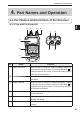
4. Part Names and Operation 4. Part Names and Operation 4-1 Part Names and Functions of the Receiver 4 4-1-1 Top and front panels (2) (1) (3) (4) (8) (7) (5) WILD 1 (6) GAIN 2ABC ATT SET 3DEF CLR MAIN MODE TONE LINK SHIFT 4 SUB NAME PRIO AUDIO STEP M V 7 PQRS 8 TUV WX ENT SCOPE 9 YZ F TUNE MW SCAN V/P/M GHI 5 JKL 6MNO 0 (9) (10) (11) No. Name Function (1) Upper main dial Rotate the dial to change the frequency/memory channel or to set items for the main band.
4. Part Names and Operation No. 4 Name Function (7) Antenna connector (SMA) Attach the supplied antenna securely. To use other antennae, select an antenna which has been tuned to operate within the specified operating frequency range. (8) Earphone jack Used to connect an external earphone. (9) Main RX lamp This lamp illuminates in green while the main band squelch is open. (10) Sub RX lamp This lamp illuminates in green while the sub band squelch is open.
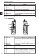
4. Part Names and Operation 4-1-3 Key operation WILD 1 GAIN ATT SET 2ABC 3DEF CLR MAIN MODE TONE LINK SHIFT 4 GHI 5 JKL 6MNO 0 SUB NAME PRIO AUDIO STEP M V 7 PQRS 8 TUV WXYZ ENT SCOPE 9 F TUNE MW SCAN V/P/M Name Function 4 After the FUNC Key Hold Down the Key Hold Down the Key is Pressed (Approx. 1 Second) and Operate the Dial 1 Enter 1. WILD key 2 Enter 2. Adjust the receiving sensitivity. 3 Enter 3. Set the Attenuator. 4 Enter 4. Switch the modulation mode. 5 Enter 5.
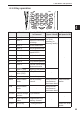
. Part Names and Operation 4-2 LCD Display (1) (2) (3) (4) (5) (6) ATH D (18) 4 MR 001 000 (1) 433.000 BUSY Indication / / (11) (12) (13) FM Function Appears when the [FUNC] key is pressed or when the Key-lock is activated (P. 63). Appears while the Auto Power OFF function is ON (P. 81). (2) (3) / (4) ATL / ATH (5) D Appears while the Detection Signal Output function is ON (P. 76). (6) / Indicates the frequency shift direction. (P.
. Basic Operation 5. Basic Operation 5-1 Turning the Power ON 1 Hold down the [POWER] key (approx. one second) to turn the power ON. Hold down the key again to turn the power OFF. 5 • Due to utilize the capacity of the battery in full to maximize the operating time, a special tune has been performed to the circuit of the DJ-X11. MEMO For this reason, you may encounter an event that the unit can’t be turned on after the battery pack is completely discharged and turned off by itself.
5. Basic Operation • When using earphones, be careful that the volume is not set too loud. Start from a low level and gradually increase it while actually listening CAUTION to the sound. When nothing is heard MEMO 5 • When the squelch is closed or the Mute function is activated, you will hear nothing even if you increase the volume level. For details, refer to the following sections “Adjusting Squelch Level” (P. 26) and “Mute Function” (P. 27).
5. Basic Operation 5-5 Monitor function The Monitor function forces the squelch to open. When receiving signals are relatively weak or are often interrupted, it opens the squelch temporarily, regardless of the current squelch level. This function is activated when the “Monitor key operation setting” (P. 87) is set to the Monitor function. There are two options for the Monitor function: PUSH and HOLD. When the [MONI] key is pressed, both options open the squelch and the “BUSY” appears on the LCD.
5. Basic Operation 5-7 Selecting the Band to Operate Select either the main band or sub band to operate. Refer to (P. 33) for the range of the receivable frequencies for each band. 1 Press the key or key to select the band to operate. 5 When the dual-band display is selected, the frequency of the selected band is displayed in larger letters. When the mono-band display is selected, only the frequency of the selected band is displayed. 2 Pressing the key or again changes the band. key BS VFO 145.
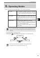
6. Operating Modes 6. Operating Modes The DJ-X11 has three operating modes: VFO, Preset, and Memory. VFO mode VFO stands for Variable Frequency Oscillator. You can select a desired frequency by rotating the dial. You can operate the receiver like a normal radio. Preset mode The audio frequencies for AM/FM radio and TV channels have alreday been set so that you can choose among them just like a conventional radio.
6. Operating Modes 6-1 Setting frequencies in VFO mode The VFO mode is a mode displayed when you turn ON the DJ-X11 for the first time with the factory default setting. In this mode, you can select receiving frequencies by rotating the dial. ● Switching between bands Pressing the or key will select the band. 6-2 Setting the Channel Step Frequency 6 A channel step refers to the interval between the frequencies which have been assigned to radio communications and broadcasts.
6. Operating Modes 6-4 Setting Frequencies through Direct Input The frequency can be directly input with the key pad. Example 1: To input 145.000 MHz WILD Press the keys and then press the Example 2: To input 0.702 MHz SET SHIFT Press the CLR keys and then press the Example 3: To input 1270.680 MHz WILD SHIFT Press the Example 4: To input 145.550 MHz WILD Press the STEP SET CLR PRIO key. STEP key. keys and then press the STEP key. keys and then press the STEP key.
6. Operating Modes 6-6 Receiving Operation 6 • Communication is not broadcasting. In most cases, communication is established when necessary using minimum facilities. It is extremely CAUTION rare for communication to send radio signals frequently. Unlike radio broadcasting, it is not always easy to receive communication.
6. Operating Modes 1 Set the mode to operate and tune to the frequency. When sig- nals are received on the selected frequency, “BUSY” and the reception level are displayed on the LCD and the received sound is heard. Moreover, the RX lamp illuminates in green. ● The range of receivable frequencies is as follows: Receivable frequencies for the main band 0.05 to 1299.99995 MHz Receivable frequencies for the sub band 144 MHz band: 118 to 170.995 MHz 430 MHz band: 336 to 469.
7. Memory Mode 7. Memory Mode Memory mode allows you to pre-program frequently-used frequencies and settings into the receiver’s memory so that you can quickly call up a desired setting. A “bank” is a location where frequencies are categorized for ease of use. Each frequency programmed to a bank is called a “channel”. In an address book of a mobile phone, a “bank” corresponds to a “group starting with A”, a “group starting with B”, and so on. A “memory channel” corresponds to individual names.
7. Memory Mode 7-2 Programming a Memory Channel This section describes how to program a memory channel with the DJ-X11. • For easy understanding, it is recommended to read this page once and then actually operate the receiver according to the programming exMEMO ample shown on (P. 37). 1 In VFO mode, set the desired frequency and the Tone Squelch function in advance. You can program the following items in a memory channel.
7. Memory Mode • Bank The relationship between the bank and the memory is as follows: Number Banks for normal memory channels (This setting may change before shipment due to the change in memory data.) PRG Bank for programmed scan channels DUAL Bank for dual band channels. A pair of frequencies for the main and sub bands are programmed in one memory channel. PRIO Bank for priority channels PASS Bank for skip-search channels BUG Bank for Bug Detector channels (Cannot be edited.
7. Memory Mode • “DUAL” can be selected only when the dual-band display is selected. • The bank for programmed scan channels requires programming of two CAUTION frequencies to channels **A and **B. Example: Assume that a frequency of 145.020 MHz is programmed to channel 01A, and a frequency of 146.100 MHz is programmed to channel 01B. The programmed scan operation scans the range between 145.020 MHz programmed to channel 01A and 146.100 MHz programmed to channel 01B.
7. Memory Mode 7-3 Calling Up a Memory Channel 1 Press the 2 Press the key to switch to Memory mode. or key to select the memory bank to call up. 3 7 Rotate the dial to select the memory channel. • When you call up the data in the bank for dual band channels, you cannot switch between the main and sub bands. CAUTION • When a frequency which is out of the range of the sub band is programmed in the memory channel with the main band, that frequency cannot be displayed with the sub band. Refer to (P.
7. Memory Mode • Once data is deleted, it cannot be restored. Ensure that you do not delete necessary data by mistake. CAUTION • To prevent important data from being deleted accidentally, be sure to reactivate the “Write-protect (memory protection) function” (P. 91) after deleting data. When you set the Write-protect function to “fail-safe”, the setting will be automatically reset to “Accepted” after the receiver is turned OFF and then turned ON again.
7. Memory Mode 7-6 Quick Memory This function is used to quickly call up memory channels which are frequently WILD used in Memory mode. Quick memory items can be programmed to the to keys. 7-6-1 Programming a memory channel to the quick memory 1 Press the key to switch to Memory mode. 2 Call up the memory channel to be programmed to the quick memory. 3 Hold down one of the WILD to keys on the key pad (approx. one second). 7 "Registered" is displayed on the LCD.