
User's Guide


CONFIGURATION APPENDIX
NEXUS MULTIPLEXOR & CONTROLLER USER GUIDE
DOC. CONTROL #8102548-000 REV 01
4
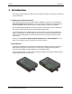
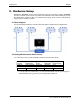
3. Connecting the System
The following procedure outlines how to connect the MUX and Controller to F800-series readers.
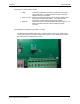
3.1. Plug the supplied F800 GPIO to DB15 adapter into the F800 GPIO port
3.2. Plug the supplied GPIO DB15 cable into the MUX GPIO to DB15 adapter and DB15 connector
of the MUX Controller
3.3. If operation from 5V USB is required, plug the supplied USB cable into the F800 USB port and
into the Controller USB port
3.4. Connect a RF coax cable between desired F800 antenna port and the MUX RF IN connector
3.5. Connect the MUX units to the Controller using standard (non-crossover) Ethernet patch cable as
follows:
3.5.1. MUX connected to F800 Antenna Port 0 MUX Controller MUX 1
3.5.2. MUX connected to F800 Antenna Port 1 MUX Controller MUX 2
3.5.3. MUX connected to F800 Antenna Port 2 MUX Controller MUX 3
3.5.4. MUX connected to F800 Antenna Port 3 MUX Controller MUX 4
3.6. Connect antennas to MUX RF Ports (Ant 0-7) using appropriate RF coax cables
3.7. Connect Power to the Reader. Power connection may be PoE or DC power source.
3.7.1. PoE connection: Connect Ethernet cable between PoE Power Sourcing Equipment and
F800
3.7.2. DC connection:
3.7.2.1. Verify the DC supply includes a ferrite. If it does not, install the required ferrite
(available from Alien) as follows”
Open the hinged ferrite
Place dc connector against one edge of the ferrite
Wrap three turns of the DC lead around the ferrite
Snap the ferrite closed
3.7.2.2. Ensure AC Plus is DISCONNECTED
3.7.2.3. Connect the DC power jack to F800 and tighten locking collar
3.7.2.4. Connect the power supply AC plug to AC power adapter
3.8. User serial or network interface to communicate with reader
3.9. Connect earth ground to the reader. The earth connection to the reader can be made by
mounting the reader on a grounded surface or connecting a ground wire using the reader
mounting features.