ALIEN TECHNOLOGY® Nexus Multiplexor & Controller ALX-2525 ALX-2530 User Guide Nexus Multiplexor & Controller
Legal Notices Copyright ©2019 Alien Technology, LLC. All rights reserved. Alien Technology, LLC and/or its affiliated companies have intellectual property rights relating to technology embodied in the products described in this document, including without limitation certain patents or patent pending applications in the U.S. or other countries. This document and the products to which it pertains are distributed under licenses restricting their use, copying, distribution and decompilation.
TABLE OF CONTENTS Alien Technology® User Guide Nexus Multiplexor & Controller Table of Contents 1. 2. 3. 4. INTRODUCTION ..................................................................................................................... 1 1.1. Who should read this manual? ....................................................................................................... 1 1.2. Introduction..............................................................................................................
CHAPTER 1 INTRODUCTION 1. Introduction This manual provides safety information, technical support information, and sources for additional product information. 1.1. Who should read this manual? This manual is written for personnel responsible for installing, configuring, and maintaining the Alien Nexus Multiplexor & Controller. This manual provides information about the features of the Nexus Multiplexor & Controller, and how to install, configure, operate, and maintain it.
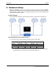
CONFIGURATION APPENDIX 2. Hardware Setup Multiplexors, ALX-2525, receive control signals and power from the MUX controller, ALX-2530. The MUX controller sources power from either the ALR-F800 series reader USB Host port, the ALR-F800 GPIO +12VDC pin #15 or an external power supply. Power source is determined by jumper inside of the MUX controller. 2.1. Block Diagram The physical interface between controller, MUX and reader is depicted in the example below: 2.2. Setting MUX Controller Power Source 2.2.1.
CHAPTER 4 BARCODE SCANNER 2.2.2.Power connection options include: USB Connect the ALR-F800 to the MUX Controller with a Type A to Type A USB cable. Power the reader from PoE or the Alien supplied AC/DC power adapter GPIO +12 VDC Power is provided to the MUX Controller from the reader GPIO port through the GPIO DB15 Cable. The reader must be powered by the Alien supplied AC/DC power adapter.
CONFIGURATION APPENDIX 3. Connecting the System The following procedure outlines how to connect the MUX and Controller to F800-series readers. 3.1. Plug the supplied F800 GPIO to DB15 adapter into the F800 GPIO port 3.2. Plug the supplied GPIO DB15 cable into the MUX GPIO to DB15 adapter and DB15 connector of the MUX Controller 3.3. If operation from 5V USB is required, plug the supplied USB cable into the F800 USB port and into the Controller USB port 3.4.
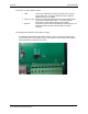
CHAPTER 4 BARCODE SCANNER 4. Mux Controller GPIO Interface There are 4 inputs and 2 outputs available to the user on the MUX Controller GPIO Connector. The MUX Controller provides its power source at the V OUT pin of the GPIO connector for use by external GPIO circuits. 4.1. Inputs: GPIO inputs of the MUX Controller are directly connected to the F800 inputs. External input circuits may be connected between V OUT and IN 0-3. 4.2.