
Setup Guide

CHAPTER 2 READER HARDWARE INSTALLATION AND OPERATION
ALR-F800 HARDWARE SETUP GUIDE
DOC. CONTROL #8102141-000 REV E
11
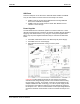
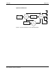
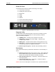
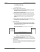
Reader I/O Panel
The I/O panel (shown below) includes the following( Left to Right):
LAN TCP/IP and PoE port
Auxiliary DC Power connector
Reset button
USB A
USB B
SDCard
9-pin D female RS-232 serial port
16-pin I/O terminal block (GPIO)
Figure 6 - ALR-F800 Reader Connections
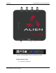
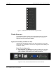
Diagnostic LEDs
The ALR-F800 includes diagnostic LEDs on the face of the reader to provide
easy and convenient external indication for various operating conditions:
On the Front Panel you will find:
POWER (green) – indicates power is applied to the reader.
CPU (green) – indicates CPU is active. (red) – indicates a fault
condition with the reader
READ (green) – indicates that the reader is receiving data from a tag.
Sniff (green) – indicates a tag signal has been detected, though it may
not be strong enough yet to complete a transaction.
Antenna Lights 0-3 (green) – indicates Active transmitting antenna.
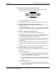
Reset button
On the ALR-F800 I/O panel you will find the reset button. The functionality is a
follows:
Hold during power up (file system recovery mode) – With a USB Flash
Drive installed with the proper system files, the reader with re-flash all
system code. (Contact Alien support for detailed procedure)
Short hold after power up (2 – 3 Seconds) – Cause the reader a soft
reboot after release.
Long hold after power up (> 10 Seconds) – Causes the reader to
return to factory settings after release.
Caution: Do not use a metal object or excessive force, to push the reset button.